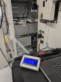
SECS-II host using a PIC18F57K42 and PIC18F47Q84

Thread Starter

nsaspook

Joined Aug 27, 2009
16,429
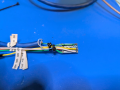
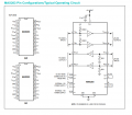
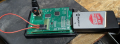
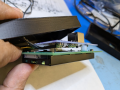
Tidy things up by moving the TTL to RS232 converter inside the case.
Use one of the small converter modules.
https://www.mouser.com/datasheet/2/609/MAX3222_MAX3241-3112280.pdf
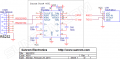
1738981429404.png
1738980951339.png
Wire it all up directly to the serial to RJ45 cable.
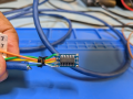
1738981005449.png
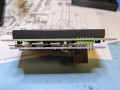
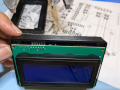
Put some shrink on it and fold it into the side and between the controller PCB and display.
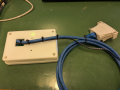
1738981102396.png
1738981120119.png
I don't plan on making many as a diagnostic tool (the IS dept normally handles fab automation, this is a engineering tool to prove our side is working when there are factory level host communications issues) but a custom PCB spin is likely, because, reasons.
Room for plenty of improvements and test routines.
1738982672925.png
 
Last edited:
Thread Starter

nsaspook

Joined Aug 27, 2009
16,429
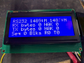
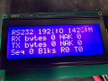
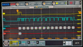
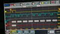
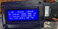
The RS232 physical line analyzer. Two ADC pins monitor a voltage divider tied to VDD and the two RS232 TX/RX lines. the ADC conversion values are converted to Mark - voltage in psec, Space + voltain in spec, Open (fault condition) and Disconnected (DB connector not connected to another RS232 device) conditions.

1739249392217.png
1739249412569.png
1739249445050.png
ADC Mark and Mark values. TX shorted to RX.
1739249500252.png
DB connector open ADC receiver Open (connected to working receiver input) and transmitter Mark values with a 86.8K series ranging resistor for +- 8 volts offsets.

1739249666579.png
ADC pins disconnected for fault generation. ADC open wiring to the RS232 pins voltage. It's the unloaded voltage divider value 2048, 1/2 of the 12-bit ADC max value 4096 (ref VDD). WIth the receiver connected the divider voltage drops to ~1920 instead of 2048 due to loading on the 12.1K divider 1% precision resistors. Easily detectable with a 12-bit ADC.


Flipping LCD buffers with the softwares VTERM capability. Up to four screen buffers can be each written to or selected for display at any time.

C:
/*
* File:  
* Author:
* Comments:
* Revision history:
*/

// This is a guard condition so that contents of this file are not included
// more than once. 
#ifndef XC_HEADER_TEMPLATE_H
#define    XC_HEADER_TEMPLATE_H

#include <xc.h> // include processor files - each processor file is guarded. 
#include <stdio.h>
#include <string.h>

#include "vconfig.h"
#include "eadog.h"
#include "timers.h"

void MyeaDogM_WriteStringAtPos(const uint8_t, const uint8_t, char *);
uint8_t update_lcd(uint8_t);
uint8_t refresh_lcd(void);
uint8_t set_vterm(const uint8_t);
char * get_vterm_ptr(uint8_t, const uint8_t);
void vterm_dump(void);
void vterm_sequence(void);
inline D_CODES display_info(void);
inline D_CODES display_help(void);
bool help_button(void);
void check_help(bool);
D_CODES set_display_info(const D_CODES);
D_CODES set_temp_display_help(const D_CODES);


#ifdef    __cplusplus
extern "C" {
#endif /* __cplusplus */

    // TODO If C++ is being used, regular C code needs function names to have C
    // linkage so the functions can be used by the c code.

#ifdef    __cplusplus
}
#endif /* __cplusplus */

#endif    /* XC_HEADER_TEMPLATE_H */
C:
// convert ADC values to char for display
                update_rs232_line_status();
               
                StartTimer(TMR_DISPLAY, DDELAY);
                if (V.vterm_switch++ >SWITCH_VTERM) {
                    set_vterm(switcher);
                    if (V.vterm_switch > SWITCH_VTERM + SWITCH_DURATION) {
                        switcher++;
                        if ((switcher & 0x03) == HELP_VTERM) { // mask [0..3]]
                            switcher = INFO_VTERM; // skip short display of the main vterm
                        }
                        V.vterm_switch = 0;
                    }
                } else {
                    set_vterm(V.vterm);
                }
                /*
                 * update info screen data points
                 */
                snprintf(get_vterm_ptr(0, INFO_VTERM), MAX_TEXT, "RS232 %hu:%c %hu:%c                ", V.v_rx_line, V.rx_rs232, V.v_tx_line, V.tx_rs232);
                snprintf(get_vterm_ptr(1, INFO_VTERM), MAX_TEXT, "RX bytes %lu NAK %lu                   ", V.rx_total, V.brn_total);
                snprintf(get_vterm_ptr(2, INFO_VTERM), MAX_TEXT, "TX bytes %lu NAK %lu                   ", V.tx_total, V.btn_total);
                snprintf(get_vterm_ptr(3, INFO_VTERM), MAX_TEXT, "Seq %lu Blks R%lu T%lu               ", V.ticks, V.bt_total, V.br_total);
                refresh_lcd();
 

Thread Starter

nsaspook

Joined Aug 27, 2009
16,429
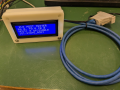
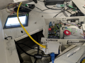
Managed to stuff all of the extra stuff inside the small enclosure. OK, need another board design just for this device. :D
1739329351048.png
1739332033848.png
Working on a quick, simple and cheap 2 layer board for JLC, with only what's needed for this application and by default (RS232 transceiver and line monitor stuff onboard) won't need extra connectors beyond the RJ45 socket and a power connector on the side.

1739329451516.png
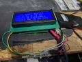
Operational testing on a processing tool.
1739329519494.png
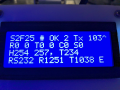
Last GEM command was stream 2 function 25. Internal state Host processing is idle (zeros). Debug mode has been enabled on the host from the equipment text terminal.
C:
/*
 * terminal response types for equipment
 */
Equipment Terminal Text Parser on the Host emulator
if (V.response.mcode == 'D' || V.response.mcode == 'd') {
        snprintf(V.info, MAX_INFO, " Debug Toggle            ");
        return CODE_DEBUG;
    }

Host code switch

            case CODE_DEBUG:
                V.debug = !V.debug;
            default:
                break;

Host LCD text display buffer setting
                    if (V.debug) {
                        snprintf(get_vterm_ptr(2, MAIN_VTERM), MAX_TEXT, "H254 %d, T%ld       ", sizeof(header254), V.testing);
                    } else {
#ifdef FAKER
                        snprintf(get_vterm_ptr(2, MAIN_VTERM), MAX_TEXT, "EQUI: %ld G:%s        #", V.ticks, GEM_TEXT[V.g_state]);
#else
                        snprintf(get_vterm_ptr(2, MAIN_VTERM), MAX_TEXT, "HOST: %ld G:%s        #", V.ticks, GEM_TEXT[V.g_state]);
#endif
                    }
1739329566454.png
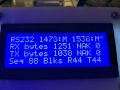
The equipment and Host emulator RS232 lines are idle Mark.
RX and TX have no NAK errors for data blocks bytes sent and received.
88 total block sequences, receive 44 and transmit 44

Cryogenic pump background noise.
 

Thread Starter

nsaspook

Joined Aug 27, 2009
16,429
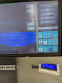
Host emulator testing on another tool type. The operator I/O is using the GEM level terminal interface that's standard for machines using the protocol.
1739994414733.png
1739994436420.png
Connected to the light-link interface of the machine controller.
1739994489386.png
Slide it to the outside for visual access up front.
1739994554423.png
Send the 'M' command from the equipment to the 'Host', the Host then sends back the 'Message' to the operator screen on the equipment. Some basic RS-232 line statistics and the Host software version number.

1739994761968.png
H for 'help', all possible host commands.

Close load lock #2
C2 command from the equipment communications terminal screen to host.
Host send SECS-GEM message to equipment to close the door.
C:
    if (V.response.mcode == 'C' || V.response.mcode == 'c') { // ready cassette load-lock control
        parse_ll();

        switch (V.e_types) {
        case GEM_VII80:
            H33[0].data[18] = '1';
            H33[0].data[17] = '6';
            break;
        case GEM_E220:
            H33[0].data[18] = '1';
            H33[0].data[17] = '0';
            break;
        default:
            break;
        }

        return CODE_LOAD;
    }

            case CODE_LOAD:
                block.respond = true;
                block.reply = (uint8_t*) & H33[0]; // S6F41 send load lock ready command
                block.reply_length = sizeof(header33);
                V.queue = true;
                set_display_info(DIS_LOAD);
                break;
C:
/*
* parse load-clock terminal command for port number
*/
static void parse_ll(void)
{
    if (V.response.cmdlen > 1) {
        switch (V.response.mparm) { // port selection
        case '1':
        case '2':
        case '3':
        case 'A':
        case 'B':
        case 'C':
        case 'a':
        case 'b':
        case 'c':
            H33[0].data[0] = V.response.mparm & 0x03;
            break;
        default:
            H33[0].data[0] = 0x01;
            break;
        }
    } else {
        H33[0].data[0] = 0x01;
    }
    V.llid = H33[0].data[0];
}

const header33 HC33[] = {//template for vii80 stack commands
    { // S2F41 'ready load-lock ' command from host to equipment
        .length = 33,
        .block.block.rbit = 0,
        .block.block.didh = 0,
        .block.block.didl = 0,
        .block.block.wbit = 1,
        .block.block.stream = 2,
        .block.block.function = 41,
        .block.block.ebit = 1,
        .block.block.bidh = 0,
        .block.block.bidl = 1,
        .block.block.systemb = 1,
        .data[22] = 0x01, // list 2 items
        .data[21] = 0x02,
        .data[20] = 0x41, // 2 ascii data
        .data[19] = 0x02,
        .data[18] = 0x31, // 1
        .data[17] = 0x37, // 7
        .data[16] = 0x01, // list 1 item
        .data[15] = 0x01,
        .data[14] = 0x01, // list 2 items
        .data[13] = 0x02,
        .data[12] = 0x41, // 8 ascii data
        .data[11] = 0x08,
        .data[10] = 0x4c, // L
        .data[9] = 0x4f, //  O
        .data[8] = 0x41, //  A
        .data[7] = 0x44, //  D
        .data[6] = 0x4c, //  L
        .data[5] = 0x4f, //  O
        .data[4] = 0x43, //  C
        .data[3] = 0x4b, //  K
        .data[2] = 0xa5, // 1 byte integer unsigned
        .data[1] = 0x01, // length 1
        .data[0] = 0x01, // value
    },

    typedef struct header33 {
        uint16_t checksum;
        uint8_t data[23];
        block10 block;
        uint8_t length;
    } header33;

    typedef struct block10_type {
        uint32_t systemb;
        uint8_t bidl;
        uint8_t bidh : 7;
        uint8_t ebit : 1;
        uint8_t function;
        uint8_t stream : 7;
        uint8_t wbit : 1;
        uint8_t didl;
        uint8_t didh : 7;
        uint8_t rbit : 1;
    } block10_type;

    typedef union block10 {
        uint8_t b[sizeof(block10_type)];
        block10_type block;
    } block10;
 
Last edited:
Thread Starter

nsaspook

Joined Aug 27, 2009
16,429
The classic problem of how do you switch something (like serial port speed) on a device with no buttons, touch screen or local I/O?

There are two serial speed rates commonly used, 19200 and 9600.
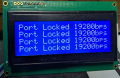
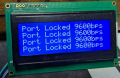
On first programming, the Host emulator alternates between those speeds with each power cycle but it's also possible to lock the serial speed with a short power-up -> power down sequence.

The saved lock state and speeds use a few bytes of NV ram from the EEPROM data space.
C:
char * s, * speed_text;
uint8_t temp_lock = false;

/*
     * Use a few EEPROM bytes to cycle or lock the serial port baud rate
     * during a power-up.
     * 9600 and 19200 are the normal speeds for SECS-I serial communications
     */
    V.speed_spin = DATAEE_ReadByte(UART_SPEED_LOCK_EADR);
    V.uart_speed_fast = DATAEE_ReadByte(UART_SPEED_EADR);
    DATAEE_WriteByte(UART_SPEED_LOCK_EADR, temp_lock); //
    DATAEE_WriteByte(UART_SPEED_EADR, V.uart_speed_fast + 1);

    if (V.uart_speed_fast % 2 == 0) { // Even/Odd selection for just two speeds
        speed_text = "Locked 9600bps"; // set default display text
    } else {
        speed_text = "Locked 19200bps";
    }
    // as soon as you see all LEDS ON, power down, quickly POWER CYCLE to LOCK baud rate
    MLED_SetHigh();
    RLED_SetHigh();
    DLED_SetHigh();
    WaitMs(TDELAY); // three seconds of delay
    RLED_SetLow(); // start complete power-up serial speed setups, LEDS OFF
    MLED_SetLow();
    DLED_SetLow();
    temp_lock = true;
    if (V.speed_spin) { // update the speed lock status byte
        DATAEE_WriteByte(UART_SPEED_LOCK_EADR, temp_lock);
    }
    DATAEE_WriteByte(UART_SPEED_EADR, V.uart_speed_fast); // update the speed setting byte

    if (V.speed_spin) { // serial speed with alternate with every power cycle
        /*
         * get saved state of serial speed flag
         */
        V.uart_speed_fast = DATAEE_ReadByte(UART_SPEED_EADR);
        if (V.uart_speed_fast % 2 == 0) {
            UART2_Initialize(); // default 9600 setup function from MCC
            UART1_Initialize();
        } else {
            UART2_Initialize19200(); // a copy of the MCC function with speed registers set for 19200
            UART1_Initialize19200();
        }

        if (V.uart_speed_fast % 2 == 0) {
            speed_text = "9600bps"; // set cycling display text
        } else {
            speed_text = "19200bps";
        }
        /*
         * ALternate the speed setting with each restart
         */
        DATAEE_WriteByte(UART_SPEED_EADR, ++V.uart_speed_fast);
        DATAEE_WriteByte(UART_SPEED_LOCK_EADR, V.speed_spin);
    } else { // serial port speed is locked
        V.uart_speed_fast = DATAEE_ReadByte(UART_SPEED_EADR); // just read and set the speed setting
        if (V.uart_speed_fast % 2 == 0) {
            UART2_Initialize();
            UART1_Initialize();
        } else {
            UART2_Initialize19200();
            UART1_Initialize19200();
        }
    }
Each power cycle lock sequence alternates the locked serial speed.
1740071339529.png
1740071429894.png
 

Thread Starter

nsaspook

Joined Aug 27, 2009
16,429
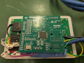
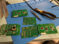
Have my V1.0 SECS-Q84 boards for this project. Fresh from JLCPCB.
1740274506518.png
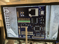
All looks good electrically and operationally, just needs some minor parts movements on the board to make things fit in the existing case a little better but much better than the prototype. with external sub-boards.
The RS232 transceiver is a MAX203EEWP that don't need external charge pump capacitors. This part is obsolete (sourcing a replacement) but I've got plenty in my local stock.
https://www.mouser.com/datasheet/2/609/MAX200_MAX213-3116555.pdf
1740324289589.png
1740274643221.png
1740274687183.png
RS-232 transceiver and voltage monitor with dual RS-232 port header for initial testing. Only the RJ45 for the RS-232 serial connection and 5V power cable will be on the production model
1740274945392.png

1740275563037.png
RS-232 ports loopback for systems host <--> equipment emulation testing.
C:
header12 H12[] = {
    { // S1F2 send 'yes, we are here ' from host
        .length = 12,
        .block.block.rbit = 0,
        .block.block.didh = 0,
        .block.block.didl = 0,
        .block.block.wbit = 0,
        .block.block.stream = 1,
        .block.block.function = 2,
        .block.block.ebit = 1,
        .block.block.bidh = 0,
        .block.block.bidl = 1,
        .block.block.systemb = 1,
        .data[1] = 1,
        .data[0] = 0,
    },
    { // S1F13 send 'online request ' from host to equipment
        .length = 12,
        .block.block.rbit = 0,
        .block.block.didh = 0,
        .block.block.didl = 0,
        .block.block.wbit = 1,
        .block.block.stream = 1,
        .block.block.function = 13,
        .block.block.ebit = 1,
        .block.block.bidh = 0,
        .block.block.bidl = 1,
        .block.block.systemb = 1,
        .data[1] = 1,
        .data[0] = 0,
    },
};
EOT and S1F1 GEM stream and function response.
1740276308438.png
1740276351615.png
The host times-out and sends a NAK because this is a testing sequence designed to generate errors.
1740276660606.png
Line and Block transfer protocol.
1740274980099.png
http://www.edgeintegration.com/downloads/Guide_to_understanding_SECS.pdf
 
Last edited:
Thread Starter

nsaspook

Joined Aug 27, 2009
16,429
Baud rate switching (cycling 9600 and 19200) with power cycle and baud rate locking (9600 or 19200) with short power bump and restart.


Thread Starter

nsaspook

Joined Aug 27, 2009
16,429
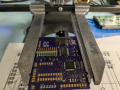
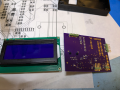
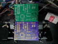
OSHPARK pcb for the final production model.
1741145805625.png
JLCPCB top OSHPARK bottom.

Just some minor changes to better fit the enclosure, clearance for connectors and cosmetics.
1741145948815.png
1741146091601.png
1741145973766.png
1741145992880.png
1741146027332.png
1741146048279.png
 
Top