Facebook
 Google
 GitHub
 Linkedin
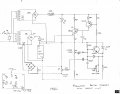
Would like some help from some of you electronic whiz people understanding this control circuit. The design was taken from an industrial 3 phase 120 volt DC at 90 amp charger. Those units are still in service and have been almost trouble free for 40 plus years. In about 1984 I modified the control circuit for use on single phase 12 volt car charger rated at 25 A max. It works great. What I like about it is the current limit and the trickle charge features. The main transformer was made from an old 120/240 street light ballast. The CT I can't recall but it was probably some small 120 volt or similar transformer. It has one wrap of heavy wire from the main transformer for a primary. This is an old design with old parts by today's standards but I still plan to triplicate this board for use it two other similar sized car chargers I have in use.
Never did have a full understanding on how this thing works though. I'm OK with the UJT and the PNP transistor but when we get to the 2N2222, the diodes, anti-hunt, current limit I'm basically lost.
Anyone interested in some coaching?
TIA
Never did have a full understanding on how this thing works though. I'm OK with the UJT and the PNP transistor but when we get to the 2N2222, the diodes, anti-hunt, current limit I'm basically lost.
Anyone interested in some coaching?
TIA
Last edited: