
I am constructing a multi channel temperature data logger.
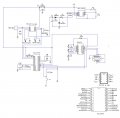
I wrote some codes in mikroC to test which channel is connected to thermocouple. The codes was attached as well. However, the result was not satisfactory. The results from RA1 pins (analouge input voltage pin) were stored in eeprom even the pin was left floating. The voltage at RA1(analouge input voltage pin) was non-zero when the input pin was left floating. I think this is electronic problem. The schematic diagram of the circuit was attached. Can someone help to figure what problem??
Thanks.
Attachments
-
 103.4 KB Views: 269
 -
1.4 KB Views: 148


