Sawtooth generation using LM339- NO 555

Thread Starter

chimera

Joined Oct 21, 2010
122
Hello!

So, Ive trying to get a saw tooth from a 5V DC source. How? Current Sourced cap and an LM339 comparator with hysteresis and an inverter using two npns.

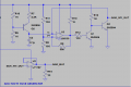
Ive attached an LTSPICE .asm SNAPSHOT because Im using an LM339 model I downloaded from the web. Really, any LT comparator would work but I wanted to stay consistent with the breadboard effort.

At any rate, the circuit seemed to simulate okay. The way the circuit works is that the pnp charges up the cap. that triggers the comparator to turn low. When that turns low, the first npn turns off and directly hard switching the second npn on and that starts to discharge the cap. At the process repeats with the hysteresis now in the picture.

I built the circuit up (breadboard) and for some reason, I see no oscillation (LOL!! Im into power electronics and normally would want to stay away from oscillations :p).. anyhow.. Ive been trying to debug it and heres what Ive gotten to so far

Vdc: 5V
Vo_Comp= LOW (0.16)
V+ = 2.43V
V-= 0.007V

Any suggestions? Please look at the attached LT SPICE .asm screen shot

Thanks
 

Attachments

Last edited:

Thread Starter

chimera

Joined Oct 21, 2010
122
Bloody Murphy's Law! Done got me again

Im apparently 'too good' to thoroughly check the pin out of the part on the data sheet. I had interchanged the comparator input pins. In hindsight..the values I was getting make sense now.

Anyways..I do appreciate Ron for at least creating a moment of 'what if' in my mind which led to the discovery of the interchanged connections.

Everything looks good. I'll post back the scope shots with the simulations and some analysis for anyone else who might eventually stumble on this post for a sawtooth wave

For those who dont know Murphy:

http://ksguy.com/site/ml4.html
 

Brownout

Joined Jan 10, 2012
2,390
Looks like Q1 does nothing more than invert the polarity of the signal for Q2. You can use one of the opamps available in the lm339 and eliminate Q1 altogether. That will clean up your circuit some. Congrats getting it to work.
 

Ron H

Joined Apr 14, 2005
7,063
Looks like Q1 does nothing more than invert the polarity of the signal for Q2. You can use one of the opamps available in the lm339 and eliminate Q1 altogether. That will clean up your circuit some. Congrats getting it to work.
Q1 AND Q3 can be eliminated, although the simulation in LTspice hangs with a "time step too small". However, the amplitude and frequency will be affected, because they are partly a function of the delays of Q1 and Q3.
And they're not op amps, they are comparators. Same symbol, big difference in function.
 
Last edited:

Brownout

Joined Jan 10, 2012
2,390
I know the difference between op-amps and comparators. Didn't look close enough to see which was being used, and I don't memorize the function of older parts (did once, but memory has faded) My point was to eliminate the transistor and clean up the circuit a little.

Hoever, that's a good point. you can eliminate Q1 too.
 
Last edited:

Brownout

Joined Jan 10, 2012
2,390
Also note that q3 does not immediately saturate when it turns on. It must first discharge the capacitor down to it's saturation voltage. As it does that, it also must sinc all of q2's current. You can improve the steepness of the trailing ramp by switching q2 off when q3 is conducting rather than leave it on all the time.
 

Thread Starter

chimera

Joined Oct 21, 2010
122
I cant get rid of Q1. When the comparator goes low, that means that the cap has charged up. Now, I need to discharge it rapidly to produce the sharp fall time associated with a saw tooth function.

So in order to implement this, I need to invert the output of the comparator, giving me the following states

Comparator low-->Turn off Q1--> turn on Q3

Comparator High-->Turn on Q1--> turn off Q3

Essentially, the function of Q1 is just there to invert the signal of the comparator. I can add an LED for visual affects or something..but that really isn't required for the design

I'll ping you guys when the analysis is complete. I just prototyped the circuit up.. debugged it for a couple of shorts and array connections.

Right now, the resulting saw tooth has a pk to pk of like 1.5V has DC offset of 2V.

That's not agreeing with the sim. Ill do some calculations again to see where the hysteresis is kicking in and check whether the calculations agree with the simulation or the prototyped version
 

Ron H

Joined Apr 14, 2005
7,063
Also note that q3 does not immediately saturate when it turns on. It must first discharge the capacitor down to it's saturation voltage. As it does that, it also must sinc all of q2's current. You can improve the steepness of the trailing ramp by switching q2 off when q3 is conducting rather than leave it on all the time.
True, but Q2's current is insignificant. Q3 is going to dump at least 100mA, what with almost 5mA of base drive. Q2's current is only around a milliamp.

Note that the hysteresis of the comparator is only about 400mV. If it weren't for the delay of the comparator, and (primarily) the storage time of Q2, that would be the amplitude of the sawtooth.
 

Brownout

Joined Jan 10, 2012
2,390
I cant get rid of Q1. When the comparator goes low, that means that the cap has charged up. Now, I need to discharge it rapidly to produce the sharp fall time associated with a saw tooth function.

So in order to implement this, I need to invert the output of the comparator, giving me the following states

Comparator low-->Turn off Q1--> turn on Q3

Comparator High-->Turn on Q1--> turn off Q3

Essentially, the function of Q1 is just there to invert the signal of the comparator. I can add an LED for visual affects or something..but that really isn't required for the design
But you have four devices in the lm339 package. You can use any of the spares to do the invertion (Q1) and then another to discharge the capacitor (Q3) so you can eliminate two transistors and their assicoated resistors. I'm not going to twist your arm and make you do it, it's just a suggestion.
 

Ron H

Joined Apr 14, 2005
7,063
But you have four devices in the lm339 package. You can use any of the spares to do the invertion (Q1) and then another to discharge the capacitor (Q3) so you can eliminate two transistors and their assicoated resistors. I'm not going to twist your arm and make you do it, it's just a suggestion.
You don't need two more sections. One more will work, because a comparator can be either inverting or noninverting. Heck, you don't even need another comparator. You can get rid of Q1 and Q3, and just feed a diode back to the capacitor from the comparator output, with the anode to the cap. Just be aware that the amplitude and frequency will change if you do either of these things.
 

Ron H

Joined Apr 14, 2005
7,063
I think if this were my circuit, I would do something like this. The hysteresis has been adjusted to ensure that the sawtooth always returns to (near) zero volts. The original circuit only has about 400mV of hysteresis, so the low level output is dependent on delay through the circuit.
 

Attachments

Top