Rotary encoder switch testing

Thread Starter

seanspotatobusiness

Joined Sep 17, 2016
210
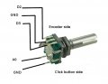
I would like to check that my rotary encoder switch is working. A video on YouTube says it can be checked using an oscilloscope but doesn't say how to connect it. I guess from pinouts that I've seen I need to connect the two pins to Vcc and GND and the other three to an oscilloscope with common GND in the middle. Are there other components required? How do I determine which pins are positive and negative? Would it be damaged by reverse polarity? Thanks.
 

Thread Starter

seanspotatobusiness

Joined Sep 17, 2016
210
Thanks very much. For the third of the three pins, the LED does not flash (confirmed by swapping leads around). It flashes for the first and the other one comes on when the encoder is depressed. I guess that means the third (top right in your circuit diagram) is faulty.
 

dendad

Joined Feb 20, 2016
4,476
Thanks very much. For the third of the three pins, the LED does not flash (confirmed by swapping leads around). It flashes for the first and the other one comes on when the encoder is depressed. I guess that means the third (top right in your circuit diagram) is faulty.
It does sound like it.
The top 3 pins are a Quadrature waveform generator so there should be 2 square wave signals produced when it is turned.
Have a search for Quadrature Encoding to see what it is used for.
 
Top