RLCC circuits and cubic expressions

Thread Starter

Muddyrunner

Joined Apr 23, 2012
2
(Hope this doesn't appear twice, as the first time I tried to post the system just locked up).

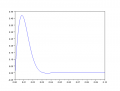
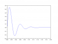
For some weeks now I have been studying what happens to RLC circuits when they are subject to a step change in applied voltage. The real-life applications for this include, for instance, DC-DC converters and full-bridge motor drive circuits, where a network composed of inductive, resistive and capacitive elements can experience a rapid change in voltage when one of the switching components changes state. My goal has been to find general equations describing current “i”, and from this equations also describing the voltages appearing across the various circuit elements. It is specifically the transient behaviour of the circuits that I am interested in.


So far I have had success with the series-RLC configuration, and one where R and C are in parallel, and that combination in series with L. In both cases I was able to use Laplace transforms to analyse the circuits and find general equations describing the currents and voltages. Also in both cases, the solutions involved transforming a second-order DE from the s-domain to the time domain. The results were found to be identical with those produced from Spice simulations of the same circuits.


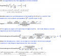
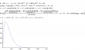
I have now moved on to a four-component configuration, and have run straight into a brick wall. After several attempts I am stuck at the same point, and I do not know how to proceed. I have laid out my working in the attached pdf, as it is rather long and I have no idea where any errors may have slipped in. The general approach I have adopted is identical to that used for the simpler (three-component) cases, but I keep getting stuck at the point where I have to transform a third-order DE.


Any pointers which anyone could offer would be gratefully received. Finally, I should also apologise for any inadvertent misuse of mathematical terminology. These aren’t the kind of discussions in which I normally become involved!


Thanks and regards,


MR.
 

Attachments

t_n_k

Joined Mar 6, 2009
5,455
Provided V is a DC source your general equations look fine. Otherwise rather than I(s)=V/(s Z(s)) one would simply write I(s)=V(s)/Z(s)

The cubic equation may or may not have all real roots so the solution will depend on finding the actual roots for particular circuit component values. If complex roots exist the outcome would be quite different to the situation with all real roots.

There is adequate literature around describing how one determines the roots of a cubic equation.
 

t_n_k

Joined Mar 6, 2009
5,455
By way of example:

Let R=25Ω, L=0.1H, C1=100uF, C2=500uF

The characteristic cubic equation becomes

\(s^3+480s^2+1000000s+8000000=0\)

which has 2 complex roots [conjugates] and one real root

- 155.87418 + 152.48301i
- 155.87418 - 152.48301i
- 168.25164

For a 10V step input this produces a current response as shown in the first attachment.

If R is changed to 10Ω the roots become

- 1127.0161
- 36.491947 + 128.11836i
- 36.491947 - 128.11836i

with the second less damped response resulting

All results, including the determination of the cubic equation roots were found using Scilab.

Edit: My gut feeling is that the characteristic cubic equation for this circuit topology will never have just three real roots. It will always be a case of one real and two conjugate complex roots - can you see why I might think is likely the case?

Edit2: My gut feeling was wrong. One needs to look at the range of values that might change the conditions to an all real roots case. If I change C1 to 10uF in the values mentioned above then for R < 28Ω the circuit has complex roots and all real roots for R>=28Ω. So one must always be careful about gut feelings.
 

Attachments

Last edited:

Thread Starter

Muddyrunner

Joined Apr 23, 2012
2
Hello t n k,

Thanks for your replies, which obviously must have taken some time to put together.

Just to clarify what it is I am trying to achieve, I have attached another pdf of a simpler worked example, which I was able to complete and verify against Spice. The results are shown in the boxed equations, and are expressions for i, VL and VRC in terms of R, L and C.

To answer the first point you raised, V is a DC source, hence the transform is V/s.

At first I wasn’t sure that your response was going to help me, mainly because I am looking for a general rather than particular solution (is that the correct terminology?) However, having taken the time to digest what you have written, and after some further Googling, it seems to me that your statement about finding the roots of the cubic is key.

If I understand correctly, I am looking to re-write my cubic in the form (x+a)(x+b)(x+c), where a, b and c are the roots of the original cubic, and values of –a, -b or –c would cause the expression to equal zero. So if my understanding is correct (and I take on board what you say about real and complex roots), then I need to find the roots of the general form of the cubic.

I searched around a bit and found this:

http://mathworld.wolfram.com/CubicFormula.html

which seems to be what I am looking for, although I have yet to work through it properly (I certainly wouldn’t take the answers at face value – I want to understand what is behind them).

On a related note, I am intrigued at how the expressions describing a circuit relate to the topology of the circuit itself. For instance, the example I have posted today is very similar to my original post, with the difference of only one capacitor. Yet the expressions describing the two are hugely different. Also, for the example I posted today, the Laplace analysis is able to “predict” the DC path through R and L – it just falls out naturally from the equations. I find that very impressive.

Anyway, enough of my rambling. Thanks once again for your help, and I’m off to read up on Cardano and Tartaglia.

Regards,

MR
 

Attachments

t_n_k

Joined Mar 6, 2009
5,455
OK hope you find the necessary answers.

With respect to the original problem you outlined a strategy ...

Intended procedure:
1. Determine an expression for impedance Z in the s-domain.
2. Determine an expression for i(s), where i(s) = V/sZ(s).
3. Re-arrange terms as necessary.
4. Transform back to the time domain, giving an expression for “i” in terms of t.


For this problem everything is fine up to point 3. Point 4 is at issue because no one general form for the current time response exists. The circuit damping has a bearing on the response type. In reality you would have three distinct possibilities. Indeed perhaps 4 or more possibilities exist as R varies from 0 to ∞.
 
Last edited:

The Electrician

Joined Oct 9, 2007
2,970
For this problem everything is fine up to point 3. Point 4 is at issue because no one general form for the current time response exists. The circuit damping has a bearing on the response type. In reality you would have three distinct possibilities. Indeed perhaps 4 or more possibilities exist as R varies from 0 to ∞.
Actually, it is possible to obtain a general expression for the current. Remember that the differential equation describing the response of a network of passive components is always a diffeq with constant coefficients, and the solution is always a sum of exponentials. The arguments to the exponentials may be complex, which is where sine and cosine functions come from.

So the general expression is simply a sum of exponentials where the arguments to the exponentials may be complex.

See the attached images.
 

Attachments

The Electrician

Joined Oct 9, 2007
2,970
If I understand correctly, I am looking to re-write my cubic in the form (x+a)(x+b)(x+c), where a, b and c are the roots of the original cubic, and values of –a, -b or –c would cause the expression to equal zero. So if my understanding is correct (and I take on board what you say about real and complex roots), then I need to find the roots of the general form of the cubic.

I searched around a bit and found this:

http://mathworld.wolfram.com/CubicFormula.html

which seems to be what I am looking for, although I have yet to work through it properly (I certainly wouldn’t take the answers at face value – I want to understand what is behind them).
In theory, you could derive a completely general, symbolic, expression for the current, but it would be extremely unwieldy because the symbolic expressions for the roots of the general cubic are themselves unwieldy.

Numerical methods to find the roots of an Nth order polynomial are readily available. It's quite reasonable to derive an expression involving the roots of the cubic and use symbolic representations of those roots in a general symbolic expression.
 

t_n_k

Joined Mar 6, 2009
5,455
Actually, it is possible to obtain a general expression for the current. Remember that the differential equation describing the response of a network of passive components is always a diffeq with constant coefficients, and the solution is always a sum of exponentials. The arguments to the exponentials may be complex, which is where sine and cosine functions come from.

So the general expression is simply a sum of exponentials where the arguments to the exponentials may be complex.

See the attached images.
Thanks Electrician - that's an excellent point. The 'convention' in the literature seems to be to attempt to differentiate the responses into the various response types as influenced by the circuit damping. Which has some merit I guess. Although there is perhaps a deeper perspective to be gained by visualizing the response in a unified manner, rather than alluding to particular responses on the basis of circuit component values.

In any case the OP can readily provide an answer to part (4) per the original learning objective. Hopefully I haven't led them astray. :)
 
Top