
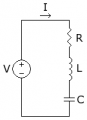
can some one explain me the qualitative aspects of RLC circuit
i not am satisfied with the vector diagrams i want the physical meaning behind
say for instance in ac with inductor when current varies induced electric field is set up which opposes the current so there is a voltage drop
similarly in capacitor it stores charges and they repel the incoming current and also for resistor
like this i want a physical explanation of RLC series circuit what happens there and also about resonance and q factor
can u explain in terms of voltage drops in inductor capacitor and resistor
see the source supplies energy to current or charges,these charges then somehow or the other they have to return to lower energy state so they drop their energy (energy is same as voltage -enegy possesed by unit charge) so they drop their voltage.All i have said till now is in
http://www.physicsclassroom.com/Clas...uits/u9l1b.cfm
my doubt is that how does this happen in RLC circuit
plz dont explain in terms of vector diagrams as it is not convincing
i want the physical meaning behind
Attachments
-
 1.7 KB Views: 186


