
I am trying to change the voltage level of a 10MHz clock signal. For this I am using LM7171 as a non-inverting summing amplifier, to DC shift the input signal, with some positive gain to reach the required voltage levels. The circuit has been soldered on a general purpose PCB and is operating at +/- 5V.
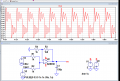
Though the simulations on LTSpice showed no problem, my output on the oscilloscope is being rippled and distorted. The distortion is not very prominent at low frequency of 100KHz, but still present.
Can someone tell me why is this happening? Do I have to make changes in my circuit design or take a new different IC? Please suggest the way out.


")


