Reduce the noise of an SMPS output

Thread Starter

Doros

Joined Dec 17, 2013
144
Dear friends hello,

I know we have (me included) discussed this issue numerous times. If you google it you will find millions answers, but I need to ask again.

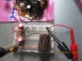
I have some SMPSs from HP inkjet printers which I would like to use them with regulators (LDOs preferably) and make DC supplies for my projects with ICs, op amps etc.

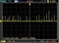
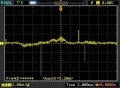
The output as you can see is noisy. I used a Π filter (it was proposed in this forum) to clean it. You can see the result.

The question is if I can further clean it, mainly the spikes and how. The values of the components are listed, 220μF electr. capacitors and 0,56mF ferrite bead.

Also because the bead is bulky, can I replace it with a coil of the same value? Will have the same result?

And finally what do you propose as an LDO? I think there is one that regulates the current too. I do not need a lot of current for my ic projects. Definitely less than one Amp

Thanks a lot for your input


Doros
 

Attachments

danadak

Joined Mar 10, 2018
4,057
Nolt all caps are equal in ESR performance -


Also your pic shows filter unloaded. makes me wonder how much
transformer action like coupling is occurring between SMPS onboard
magnetics and your filter.

Grounds out to filter look L due to lead length, that will aggravate problem.

Add .01 and .1 uF ceramic disk in parallel with filter caps. Ceramic ESR takes
over where electrolytic ESR falls off in frequency domain.

Look at actual Cap datasheets, not all equal capacitance and V caps perform
the same. Some better than other due to construction and material variations.

Turn you filter L perpendicular (its windings) to SMPS magnetics, that will drop L coupling.

Your load for the SMPS looks like it is connected to input side of filter, rather
than its output ?


Regards, Dana.
 
Last edited:

Thread Starter

Doros

Joined Dec 17, 2013
144
Thanks Dana,

Just some questions below.

Also your pic shows filter unloaded. makes me wonder how much transformer action like coupling is occurring between SMPS onboard
magnetics and your filter.


You mean the SMPS should be in a metal box as a Faraday cage with the filter outside?

Grounds out to filter look L due to lead length, that will aggravate problem

You are talking about the ferrite bead? I was experimenting that's why the long leads. Another question about this, is if I can use any ferrite bead as long as it can stand the current? I need not a bulky one

Add .01 and .1 uF ceramic disk in parallel with filter caps. Ceramic ESR takes
over where electrolytic ESR falls off in frequency domain.

Look at actual Cap datasheets, not all equal capacitance and V caps perform
the same. Some better than other due to construction and material variations.


I will do it

Turn you filter L perpendicular (its windings) to SMPS magnetics, that will drop L coupling.

When I build the filter, my intention is to use not such a bulky ferrite bead, and I will take into consideration the above

Your load for the SMPS looks like it is connected to input side of filter, rather
than its output ?


When I was experimenting with the filter I used a 1Kohm resistor to have some current just after the SMPS. The load in reality will be after the regulator that I will use. An LDO preferably

Thanks a lot for your input

regards

Doros
 

danadak

Joined Mar 10, 2018
4,057
You mean the SMPS should be in a metal box as a Faraday cage with the filter outside?
No, that should not be necessary. Just be aware of magnetic coupling issues/layout.


You are talking about the ferrite bead? I was experimenting that's why the long leads. Another question about this, is if I can use any ferrite bead as long as it can stand the current? I need not a bulky one
Focus on lead ground length SMPS to filter, and ground capability in a solderless breadboard, just not an ideal
situation.

When you put caps in short leads, added L from lead length your enemy.


Regards, Dana.
 
Top