
 Facebook
 Google
 GitHub
 Linkedin

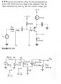
My only question has to do with his small signal model representation.
With an NPN transitor like so, current should flow down into the emitter, out and to the left of the base and down through the collector right?
So in his small signal representation, should the current from the current source be flowing from emitter to collector or does he have it correct?
If so, why?
With an NPN transitor like so, current should flow down into the emitter, out and to the left of the base and down through the collector right?
So in his small signal representation, should the current from the current source be flowing from emitter to collector or does he have it correct?
If so, why?
Attachments
-
 42.5 KB Views: 23






