Question, What are Pros and Cons of rectified SCR output used as PM DC motor speed control

Thread Starter

WodWrkr

Joined Sep 23, 2015
12
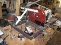
Treadmill motor used to power a belt sander. I initially controlled the speed using the original "large" treadmill user control panel. Wanted smaller so was looking to use an MC-60($50-100) board and pot but saw an 10000w SCR($20 give or take) and bridge rectifier used to do it in a YouTube video. I don't recall the link posting rules on this forum so I will post it this way. https : //www . youtube . com/watch?v=_NmAFZMAfH8 (take out the spaces around the colon and periods if you want to see it). I bought the components and bench tested it, was afraid it would be noisy but it was amazingly quit and seemed to work like a charm. Does anyone know if there may be some "cons" to doing this. The "pros" are pretty much self evident.
 

Attachments

MaxHeadRoom

Joined Jul 18, 2013
28,684
The PWM controllers off ebay are about the same price and superior over Triac controlled type.
But in both cases there are refinements with the MC-80 or one of the KB style controllers that you don't get with the $5.00 ones, namely no current safety limit and ramp up/accel/decel control.
If that one works for you then go for it, there is no real CON except the price.
Max.
 

Thread Starter

WodWrkr

Joined Sep 23, 2015
12
On cons I was thinking along the lines of SCR voltage spikes or similar problems maybe breaking down the motor windings or something like that. Don't have a scope so don't know what the rectified wave form might look like. Could it use some capacitance filtering. The ferrite ring was actually on the 120vac input circuit on the original treadmill setup. I put it in the DC output lines to help the motor a little.
 

MaxHeadRoom

Joined Jul 18, 2013
28,684
The SCR control is two diodes of a bridge across the incoming AC, there is usually little filtering except the Ferrite inductors you mention, these are not for the benefit of the motor though, and some have a low freq common-mode choke in the motor leads.
You cannot put capacitance across the bridge.
Max.
 

Thread Starter

WodWrkr

Joined Sep 23, 2015
12
The SCR control is two diodes of a bridge across the incoming AC, there is usually little filtering except the Ferrite inductors you mention, these are not for the benefit of the motor though, and some have a low freq common-mode choke in the motor leads.
You cannot put capacitance across the bridge.
Max.
Thanks Max, appreciate the feedback.
 

Thread Starter

WodWrkr

Joined Sep 23, 2015
12
The SCR control is two diodes of a bridge across the incoming AC, there is usually little filtering except the Ferrite inductors you mention, these are not for the benefit of the motor though, and some have a low freq common-mode choke in the motor leads.
You cannot put capacitance across the bridge.
Max.
Max, just wanted to make sure we were talking apples and apples. I have attached a circuit diagram of the configuration I was referring to. Any added capacitance would be across the output of the output bridge rectifier and/or motor load. Is that what your "You cannot..." was referring to or was it inside the SCR bridge circuit?
 

Attachments

MaxHeadRoom

Joined Jul 18, 2013
28,684
It is not customary to use a large electrolytic on the motor leads in this case, in some cases a choke is used as mentioned earlier.
Max.
 
Top