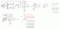
Im wondering if it is possible to set up a 555 to have a variable frequency and keep a fixed duty cycle, for instance, 50% at 1hz, and variable to say, 50% at 100 Hz,
Or maybe set it up so it keeps an on time of 10%, so it would make a quick on pulse every second, or quick pulses 100 times a second. Both change as the frequency is adjusted.
the other side I want to try is to make one that keeps a constant on time while changing the frequency, so if the on pulse is on for .01 sec at 1 Hz, can it have the same on time at 100Hz, and only vary the off time...
you understand what im tryin to say?
Thanks in advance