Project : Mono Preamp

Thread Starter

Wendy

Joined Mar 24, 2008
23,421


I've been tagged (volunteered actually) to assist a group with their sound system. Boom boxes with removable speakers are good for this, but sometimes you need a bit of amplification between the wireless mic receiver and the main amplifier.

This design has a variable gain between 1 to just over 20. I measured a max gain of 21.7. I made the lid using a 3D printer, which was a luxury. You can adapt the dimensions given to a conventional lid. For those lucky souls who have access to a 3D printer I included the .stl file.

The frequency response was flat up to 100Khz, and I saw low role off around 20 Hz (theoretical is 16Hz).

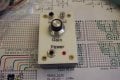
Here is the breadboard and schematic:


The parts not on the parts list were:

Project Box - BG Micro Part Number ACS1157 ($2.01)
Wall Wart DC Power supply - 9VDC to 18VDC
Matching Power Input Jack for wall wart
U1 - NJM4565 (I suspect almost any decent dual op amp will work, but this one is designed for low noise).

This project is very low power, almost any DC wall wart in the voltage range will work. Do make sure the wall wart is completely isolated from the AC line. I have made a prototype before this one shown which will be recycled, and will make 2 more before I am done. I was aiming for maximum simplicity as well as performance.

.
 

Attachments

Last edited:

Thread Starter

Wendy

Joined Mar 24, 2008
23,421
OK, I built S/N 002, shown below:


For the halibut I put in a 1458, which is a dual op amp only slightly better than a 741. The amazing thing to me is it worked at all, but to give you a comparison I took 2 pictures, both at 10Khz and just shy of clipping. I used a square wave because it is loaded with harmonics and is a good test waveform.

1st, the 1458


Next, the JCR4565


The high frequency roll off is immediately obvious. To anyone who knows both op amps this comes as no surprise, but I thought the new folks might find it interesting.

.
 

Attachments

bloguetronica

Joined Apr 27, 2007
1,541
Hi Bill,

Nice amp! May I suggest the LM4562 (aka LME49720)? It has very low noise and THD (0.00003%), so it fits well into your application.

Regards, Samuel Lourenço
 

Thread Starter

Wendy

Joined Mar 24, 2008
23,421
Funny thing, I got the JCR4565 as samples from Tanner's electronics. I've bought more since then. I have some other projects I'm going to audition them in.
 

Thread Starter

Wendy

Joined Mar 24, 2008
23,421
Yes, I do. I'll fix it tonight when I have more time. Thanks.

_________________________________________________

Done.
 
Last edited:

THE_RB

Joined Feb 11, 2008
5,438
Maybe a metal box would be a good idea too Bill?

With a large signal input the EMI noise etc will be low compared to the signal, but it's possible someone might want to use this with a low output guitar or mic, where a shielded box would be of benefit.
 

Thread Starter

Wendy

Joined Mar 24, 2008
23,421
Maybe a metal box would be a good idea too Bill?

With a large signal input the EMI noise etc will be low compared to the signal, but it's possible someone might want to use this with a low output guitar or mic, where a shielded box would be of benefit.
Whoever needs that application could definitely use a metal box, I was after a decent look and good performance. If you want to pick up AC hum just park your stuff too close to the Oscope though.

I told my friend at the time I wasn't too worried about the plastic color. I tried very hard to make the labels as part of the lid, but the software (not the printer) wasn't up to it. No big deal though, these suckers are usually parked in back of the amplifier.

Did I mention one of my near future projects is a 100W class D amp?
 

arenwi

Joined Dec 29, 2014
37
Hi Bill,

I had a post asking for solution for an amplifier and it cames to heare, many tahnks

About your schematic. I found the virtual ground circuit in the midle of the schematics.
The left circuit is the amplifier and you only use the virtual ground to reference for the imput and output?? nothing more in the circuit?? The rest of the circuit are with the normal grouns??

Ok I´ve never test the ground of the microphone and output conected to the virtual ground. It sound a solution of mi problem¡¡¡¡

I will tell something
 

Thread Starter

Wendy

Joined Mar 24, 2008
23,421
A virtual ground created by the op amp as shown is very low impedance. It can not take a lot of current, but to a signal both its AC and DC characteristics are much less than 1Ω. This makes it ideal to use as a ground in a AC amplifier.

Note that R3 is going to virtual ground, and will allow the op amp to use the configurations we all know and love, and can predict with great accuracy. You want 600Ω input? Make R3 600Ω and that is what it is.
 

cmartinez

Joined Jan 17, 2007
8,255
Great circuit.... question, shouldn't R6 be 470 Ω instead of 4.7K ?
Won't the LED burn too dimly with R6 being that high?
EDIT: never mind... I just noticed the 9-20V allowed power input range... I'm too used to working at 5V TTL ...
 

Thread Starter

Wendy

Joined Mar 24, 2008
23,421
Actually, for a lot of these circuits dim is good. Modern LEDs can be bright, and overwhelm everything around them, when all you really want is notice that there is power to the gadget.
 

cmartinez

Joined Jan 17, 2007
8,255
Actually, for a lot of these circuits dim is good. Modern LEDs can be bright, and overwhelm everything around them, when all you really want is notice that there is power to the gadget.
Right... now I recall that most musical instruments amps have LEDs that burn dimmer than circuits used for other purposes... wonder if it's aesthetics, since bands play mostly in the dark at night clubs and the like...
 
Top