Facebook
 Google
 GitHub
 Linkedin
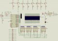
Circuit file
I'm working on how to use 89x52 and 74HC595 to multiplex a 8x32 LED matrix. I was able to use column scanning method, but when I changed to row scanning, it went awful. Even when I remove the delay, it still scans really slow. Is it because of my circuit design ? I need help. Thank you in advance.
P.S: I want to master both row and column scanning so, please, don't suggest using column scanning...
Rich (BB code):
#include<at89x52.h>
sbit DATA = P0^0;
sbit SCK = P0^1;
sbit SCL = P0^2;
	unsigned char code hang[]={
	0xFF,0xFF,0xFF,0xFF,0xFF,0xFF,0xFF,0xFF,
	0xFF,0xFF,0xFF,0xFF,0xFF,0xFF,0xFF,0xFF,
	0xFF,0xFF,0xFF,0xFF,0xFF,0xFF,0xFF,0xFF,
	0xFF,0xFF,0xFF,0xFF,0xFF,0xFF,0xFF,0xFF,
	0xC3,0xBD,0xBD,0xBD,0xBD,0xBD,0xBD,0xC3,
	0xFF,0xFF,0xFF,0xFF,0xFF,0xFF,0xFF,0xFF,
	0xFF,0xFF,0xFF,0xFF,0xFF,0xFF,0xFF,0xFF,
	0xFF,0xFF,0xFF,0xFF,0xFF,0xFF,0xFF,0xFF,
	0xFF,0xFF,0xFF,0xFF,0xFF,0xFF,0xFF,0xFF
	};
unsigned char cot[8]={0x80,0x40,0x20,0x10,0x08,0x04,0x02,0x01};
int n,k;
void delay(unsigned long time)
{
	while(time--)
	{
		_nop_();
	};
}
void quet(unsigned char x)
{
	unsigned char i, temp;
	for (i=0;i<8;i++)
	{
	SCK	= 0;
	temp = x;
	temp = temp&0x80;
	if (temp==0x80)
		DATA = 0;
	else DATA = 1;
	x*=2;
	SCK = 1;
	}															 **
}
void main()
{
	while(1)
	{

	for(n=0;n<8;n++)
	{
	SCL = 0;
	quet(0xFF);
	quet(0xFF);
	quet(0xFF);
	quet(hang[4*8 + n]);
	P2 = ~cot[n];
	SCL = 1;
	}
	}
}P.S: I want to master both row and column scanning so, please, don't suggest using column scanning...
Last edited: