problem in making negative voltaqge via 7905

Status
Not open for further replies.

Thread Starter

eric_s88

Joined Apr 20, 2011
158
Hi everyone,
I have a problem in designing a circuit to make a negative 5V voltage via 7905 voltage regulator.

in a circuit I need to have a +5V and a -5V as AtoD supplies, so I've used these to IC > 7805 (+5V) & 7905(-5V) .

I have connected a 12V power supply directly to the inputs of mentioned ICs, and the GND is common between them , but in the output of 7905 I have +5V.. whats the problem??? :confused:

does 7905 need a driving circuit?? whats that, can anybody help me with a schematic??

thank you

Eric
 

vam3kor

Joined Jul 18, 2011
5
Hai

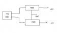
try the attached circuit. connect power supply ground to only the input of 7905.
Don't connect the 7805 and 7905 ground with power supply ground
that means power supply ground and regulators ground are different
try this and let me know the result

normally we need full wave rectifier with center tapped transformer to acheive +5 and -5.
 

Attachments

t_n_k

Joined Mar 6, 2009
5,455
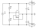
You could possibly "stiffen" the virtual ground with a simple resistive voltage divider or an op-amp driven enhancement. General idea in attachment with certain caveats.

The supply 12V DC total will not be sufficient to keep the two 5V regulators operating within their linear regulation conditions. The drop-out difference is typically 2V for the 7805 & 7905. So you would probably need 15V DC to run both with a virtual ground.

A further issue will be the existence of any substantial current magnitude imbalance between the +5V and -5V loads.
 

Attachments

Last edited:

PeeSeeBee

Joined Jun 17, 2011
56
Hi everyone,
I have a problem in designing a circuit to make a negative 5V voltage via 7905 voltage regulator.

in a circuit I need to have a +5V and a -5V as AtoD supplies, so I've used these to IC > 7805 (+5V) & 7905(-5V) .

I have connected a 12V power supply directly to the inputs of mentioned ICs, and the GND is common between them , but in the output of 7905 I have +5V.. whats the problem??? :confused:

does 7905 need a driving circuit?? whats that, can anybody help me with a schematic??

thank you

Eric
What is the polarity of the input voltage of the 7905? It sounds like you are supplying both regulators with +12v.

The 7905 will not convert +12v to -5v. It needs -12v on its input terminal.

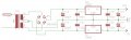
The attached circuit shows how to use a centre tapped transformer to build a +/- 5v supply.

btw...don't forget that the 7805 & 7905 have different pinouts.
 

Attachments

Last edited:

Thread Starter

eric_s88

Joined Apr 20, 2011
158
Hi guys thanks for your supporting ;)

vam3kor : I've tried your schematic and I received +5V on the output of 7805, but I have only -2.5V on the output of 7905, I used +18V voltage as circuit input, I have no idea why it doesn't work.

t_n_k: I will try your schematic and I'll post the result, but I have a question, whats the role of the op-amp?? does it make the virtual ground?

PeeSeeBee : yes I think it would help , but the problem is I'm using a Switching power supply , is there any way to build a +/-5v supply without using a transformer??

Thank you

Eric
 

Thread Starter

eric_s88

Joined Apr 20, 2011
158
t_n_k : I have tried your schematic , and its working and I now have +/-5V in outputs, would you explain the operation of the circuit and the elements duty?? :)

thank you

Eric
 

t_n_k

Joined Mar 6, 2009
5,455
t_n_k : I have tried your schematic , and its working and I now have +/-5V in outputs, would you explain the operation of the circuit and the elements duty?? :)

thank you

Eric
It's a fairly basic concept. The op-amp is configured as a voltage follower. The input is set by the 2x10k resistive divider to half the supply voltage. So the op-amp output drives the common connection of the two voltage regulators to the mid-point of the source voltage. This driving point is used as the virtual ground.

A potential problem arises when the imbalance between the +5V and -5V output load currents becomes substantial. The op-amp has to supply the magnitude difference. If the difference was say >100 mA then the op-amp may not have the necessary output capacity to do this whilst maintaining a fixed virtual ground output at half the supply voltage. One could probably get around this by using a correctly rated bipolar BJT (NPN-PNP) follower pair in the amplifier output / feedback path.
 
Status
Not open for further replies.
Top