
I have made an FM transmitter on a breadboard using a single transistor, BC547... Sometimes I can hear the music on my cell phone at a frequency of 100.35 MHz but mostly its all noisy... What can I do to remove the noise??? I am using a battery of 9V. Will a voltage regulator help in reducing noise?? Also plz tel any precautions to be taken when i build the circuit on a simple circuit booard... Plz help... Thanx
Problem in FM transmitter
- Thread starter prsarr
- Start date
Scroll to continue with content
TecknoTone
- Joined May 20, 2012
- 21
Breadboards are not suitable for RF circuits as there is too much stray capacitance.
praondevou
- Joined Jul 9, 2011
- 2,942
I have made an FM transmitter on a breadboard using a single transistor, BC547... Sometimes I can hear the music on my cell phone at a frequency of 100.35 MHz but mostly its all noisy... What can I do to remove the noise??? I am using a battery of 9V. Will a voltage regulator help in reducing noise?? Also plz tel any precautions to be taken when i build the circuit on a simple circuit booard... Plz help... Thanx
Yes, breadboard is not good and also: Where is the schematic and breadboard layout picture?
Noise free reception using FM relies on a number of things:-I have made an FM transmitter on a breadboard using a single transistor, BC547... Sometimes I can hear the music on my cell phone at a frequency of 100.35 MHz but mostly its all noisy... What can I do to remove the noise??? I am using a battery of 9V. Will a voltage regulator help in reducing noise?? Also plz tel any precautions to be taken when i build the circuit on a simple circuit booard... Plz help... Thanx
( 1)Signal strength--Your BC547 will be really battling to produce much power at 100MHz,plus the FM receiver in your cell phone is not very sensitive.
This means that you will lose noise immunity.
(2) Sufficient frequency deviation-The FM Broadcast system standard is +- 75kHz max deviation.
Anything much less than that causes the demodulated signal to be very low in amplitude,so that the lowest level passages of music will be eclipsed by circuit noise.
You are unlikely to achieve a lot of deviation in such a simple circuit.
(3) Frequency Instability---- Although the FM receiver is quite wideband,
self-excited oscillators at 100MHz or so can easily drift out of the passband,& the receiver will need retuning.
All these limitations mean your received audio will be very low level & noisy,& make it unlikely that the thing will ever be anything but an interesting experiment.
DickCappels
- Joined Aug 21, 2008
- 10,170
Yes, by all means, post the circuit. Also, please describe the noise you are hearing and the audio signal you are feeding into the transmitter (over driving the transmitter can make the signal sound noisy on the FM receiver). Oh yeah...and get rid of the breadboard.
nisar.wazir
- Joined Sep 16, 2016
- 2
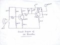
i design this circuit but the problem i face is i see no current flow in this circuit
what should i do now ?
what should i do now ?
DickCappels
- Joined Aug 21, 2008
- 10,170
Please post a schematic of your circuit and if possible a photograph of it.
this circuit is not working properly so ,plz face difoult and solve my problem soon
Attachments
-
 125.4 KB Views: 68
Configuration looks reasonable. Double check that resistor you have in the emitter of the audio amp stage - 150K is way too high.
With the antenna connected directly to the collector of the oscillator, the frequency is going to vary as you move the antenna around, or as you move around the antenna. Might want to connect the antenna to a tap on the coil near the +9 volt end to reduce loading.
With the antenna connected directly to the collector of the oscillator, the frequency is going to vary as you move the antenna around, or as you move around the antenna. Might want to connect the antenna to a tap on the coil near the +9 volt end to reduce loading.
DickCappels
- Joined Aug 21, 2008
- 10,170
I think there is a problem with the emitter resistor in the first transistor. It says "100k" which when combined with a 10k collector resistor will get you a voltage gain of 1/10 or -20 db. That emitter resistor should probably be more like 4.7k.
Last edited:

Sohampal.101
- Joined Jan 28, 2018
- 1
I made a 2 transistor fm transmitter but it seens like it doesn't work. The schematic and real image is attached, i used 2n222a transistors in place of 2n3904.

Attachments
-
 15.5 KB Views: 3
Last edited by a moderator:
I've never used that construction technique. But, my first question would be 'what kind of wire are you using to connect the various nodes? If looks like enameled magnet wire, and many of the junctions do not look like you removed the enamel. Second, lead lengths are rather long in the RF area. In particular the bypass cap in the base of Q2 has a lot of inductance (lead length) in series with it. Circuit wise, you really should have some capacitive bypassing between the positive supply rail and ground.
For others, looks like this came from here:
http://lucidscience.com/pro-basic spy transmitter-1.aspx
For others, looks like this came from here:
http://lucidscience.com/pro-basic spy transmitter-1.aspx
Last edited:
Assuming that the enamel has been scraped off the connection wire where it wraps around the nails, a dab of solder at those points will ensure that there are no loose connections (and that means one less thing to worry about). But the two main problems with the circuit are (1) the lack of a bypass capacitor between the positive connection (the wire marked +3 to 9 volts) and ground. A 10n cap should do the trick. (2) You have used a fixed ceramic cap for C5 instead of the 10 - 50pF trimmer specified in the schematic. The trimmer is needed to tune the transmitter to the frequency of your receiver, otherwise even if it is transmitting you will never know that it is. The music that you intermittently hear is probably due to the transmitter temporarily overloading the front-end RF amp of your cell-phone's receiver, making it into a mixer of sorts, which is picking up nearby radio stations transmitting music.
This construction technique is not appropriate for 100 Mhz RF circuits.
The length of wire between components becomes a significant inductance, each nail forms a capacitor between all other nearby nails, and ground.
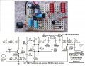
This picture shows a typical FM transmitter kit, parts are mounted close together to minimize the stray inductance, connection points are small to minimize stray capacitance.

The length of wire between components becomes a significant inductance, each nail forms a capacitor between all other nearby nails, and ground.
This picture shows a typical FM transmitter kit, parts are mounted close together to minimize the stray inductance, connection points are small to minimize stray capacitance.
The circuit with the green and pink background has the audio transistor biased wrong for any battery between 3V and 9V. It has a 0.22uF capacitor cutting all audio frequencies above 100Hz at the collector of the audio transistor instead of using pre-emphasis to boost all high audio frequencies that FM transmitters are supposed to have.
I re-designed a transmitter like the first one in this thread and built it compactly on stripboard. I used a low dropout voltage regulator and biased the audio transistor correctly. The voltage regulator also powers the RF oscillator so the radio frequency does not change as the battery voltage runs down. I added pre-emphasis so it sounds great. I added an RF amplifier transistor to isolate the oscillator from the antenna so the radio frequency does not change when something moves towards or away from the antenna.
I re-designed a transmitter like the first one in this thread and built it compactly on stripboard. I used a low dropout voltage regulator and biased the audio transistor correctly. The voltage regulator also powers the RF oscillator so the radio frequency does not change as the battery voltage runs down. I added pre-emphasis so it sounds great. I added an RF amplifier transistor to isolate the oscillator from the antenna so the radio frequency does not change when something moves towards or away from the antenna.
Attachments
-
 354.1 KB Views: 45
 -
 196 KB Views: 54
My FM transmitter was designed to be heard clearly on a high quality FM hifi or car radio 2km away as tested across a large river valley so its 9V current is 53mA. This much power is illegal without a license so don't tell the government. If its current is reduced to 5mA then its range will be reduced to about 200m to a high quality radio or across the room to a cheap radio.
A single wire antenna 30 inches long and broadside to the radio antenna like I used works fine but a dipole twice the length or a pretty large yagi antenna is very directional and peaks the distance.
My FM transmitter is very stable since it has a voltage regulator, an output RF amplifier that isolates the oscillator from the antenna and uses a circuit board, not a solderless breadboard.
On my FM transmitter, trimmer capacitor C6 adjusts the radio frequency of the oscillator and trimmer capacitor C13 peaks the RF amplifier output at that frequency.
I tweaked the capacitor values on a simulator program:
Attachments
-
 29.8 KB Views: 39
| Thread starter | Similar threads | Forum | Replies | Date |
|---|---|---|---|---|
| C | Need help with FM Radio Transmitter / Amplifier | Wireless & RF Design | 14 | |
| V | Problem with transmitter | Wireless & RF Design | 8 | |
|
|
433MHz Wireless transmitter and receiver problem | General Electronics Chat | 9 | |
| H | problem in my Fm transmitter | General Electronics Chat | 11 | |
| V | FM Transmitter audio problem | General Electronics Chat | 3 |
You May Also Like
-

New Avalanche Photodiode IR Sensors Reported as 12X More Sensitive
by Aaron Carman
-

Nordic, MediaTek, and U-blox Take on New Wireless Frontiers
by Jake Hertz
-

Samsung, Micron, and SK Hynix Lead the Charge on HBM3E DRAM
by Duane Benson
-

Siemens Rolls Out Multi-Discipline Simulation Tool for EV Designs
by Jake Hertz