
Powering LED's from powerbank
- Thread starter Semsvh
- Start date


Scroll to continue with content
Hi Sem,
Do you have a circuit diagram to post that was used to create the PCB artwork?
E

jiggermole
- Joined Jul 29, 2016
- 161
it will kind of work. Your specification on the job isn't the greatest. You specified a power bank that can supply 3A but your list of leds and their operating current adds up to 7A so your specification is failed from the start.
and unless they specified it, those are rendered as 1/4 watt resistors and they are going to be dropping way more than that. The uv ones will be dropping 0.7 watts each.
and unless they specified it, those are rendered as 1/4 watt resistors and they are going to be dropping way more than that. The uv ones will be dropping 0.7 watts each.
Thanks for your response!it will kind of work. Your specification on the job isn't the greatest. You specified a power bank that can supply 3A but your list of leds and their operating current adds up to 7A so your specification is failed from the start.
and unless they specified it, those are rendered as 1/4 watt resistors and they are going to be dropping way more than that. The uv ones will be dropping 0.7 watts each.
The initial order was more detailed but please keep in mind im very very new to electronics . I was thinking of using the LED's in series with an voltage multiplier but hired the freelancers to help me with the design because my knowledge is not sufficient enough in electronics to design it myself. Do you have any tips to make it work that i can ask the freelancers to revise?
The powerbank has 2 outputs, both 5V 3A max. Will it work better if i power the pcb with the 2 ports parralel to stack the current to 6A?it will kind of work. Your specification on the job isn't the greatest. You specified a power bank that can supply 3A but your list of leds and their operating current adds up to 7A so your specification is failed from the start.
and unless they specified it, those are rendered as 1/4 watt resistors and they are going to be dropping way more than that. The uv ones will be dropping 0.7 watts each.
Jerry-Hat-Trick
- Joined Aug 31, 2022
- 596
From the selected resistor values it looks like the target current through each LED is around 500mA so you are maybe looking at a total current through eight LEDs in parallel of around 4A. Can you use two USB outputs from the powerbank, splitting the LEDs between them?
You could get back to 3.5A by putting the two blue LED's in series, maybe with a small value resistor in series but not strictly necessary. The added advantage is that you avoid dropping 2.5V across a resistor which would dissipate 1.25 Watt.
How sure are you that 500mA through each LED is the current you want? If you can live with maybe 400mA you can increase resistor values to reduce the overall current to 3.5 x 400/500 = 2.8A. With your existing design the UV resistors dissipate around 0.7 watt and the green and white resistors around 0.85 watt so even 1 watt resistors are marginal. Again, dropping to 400 mA reduces the power but 1 W resistors are still necessary. I've used four 1/4 resistors instead - two in series in parallel with another two in series, so the overall resistance is the same as the four individual resistors.
You could try a boost converter to boost the voltage. Presumably you intend this with your "voltage multiplier"? You will lose some power in the conversion, but it is possible and you'd probably win more power saving than you lose. But it adds complexity and probably cost, so if splitting between two power bank outputs or reducing overall current is acceptable I'd try that first.
EDIT: Oops, just read your last post. Personally, I wouldn't parallel up the outputs, just split the circuit into 2 x 4 LEDs. The rest of my post is still relevant I think
Thanks Jerry for your excellent feedback. I will split the circuit into 2 x 4 LED's with 2 powerbank outputs .From the selected resistor values it looks like the target current through each LED is around 500mA so you are maybe looking at a total current through eight LEDs in parallel of around 4A. Can you use two USB outputs from the powerbank, splitting the LEDs between them?
You could get back to 3.5A by putting the two blue LED's in series, maybe with a small value resistor in series but not strictly necessary. The added advantage is that you avoid dropping 2.5V across a resistor which would dissipate 1.25 Watt.
How sure are you that 500mA through each LED is the current you want? If you can live with maybe 400mA you can increase resistor values to reduce the overall current to 3.5 x 400/500 = 2.8A. With your existing design the UV resistors dissipate around 0.7 watt and the green and white resistors around 0.85 watt so even 1 watt resistors are marginal. Again, dropping to 400 mA reduces the power but 1 W resistors are still necessary. I've used four 1/4 resistors instead - two in series in parallel with another two in series, so the overall resistance is the same as the four individual resistors.
You could try a boost converter to boost the voltage. Presumably you intend this with your "voltage multiplier"? You will lose some power in the conversion, but it is possible and you'd probably win more power saving than you lose. But it adds complexity and probably cost, so if splitting between two power bank outputs or reducing overall current is acceptable I'd try that first.
EDIT: Oops, just read your last post. Personally, I wouldn't parallel up the outputs, just split the circuit into 2 x 4 LEDs. The rest of my post is still relevant I think
Audioguru again
- Joined Oct 21, 2019
- 6,789
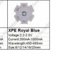
Please check the datasheet for the blue LEDs. A modern blue LED has a forward voltage of 2.85V or more.
Each UV LED has three chips in series which is why the forward voltage is 3 times higher than a single UV LED.
I agree that your tiny resistors will quickly fry and maybe also your eyes.
How will you cool the LEDs?
Each UV LED has three chips in series which is why the forward voltage is 3 times higher than a single UV LED.
I agree that your tiny resistors will quickly fry and maybe also your eyes.
How will you cool the LEDs?
Is 3A the maximum current rating, or is the powerbank capacity 3Ah?a 5V 3A powerbank.
26800mAh = total capacity of the powerbank.Is 3A the maximum current rating, or is the powerbank capacity 3Ah?
The powerbank has 3 output ports. (5V, 3A current max per output port. Total max output current is 6A)
Hi Audioguru,Please check the datasheet for the blue LEDs. A modern blue LED has a forward voltage of 2.85V or more.
Each UV LED has three chips in series which is why the forward voltage is 3 times higher than a single UV LED.
I agree that your tiny resistors will quickly fry and maybe also your eyes.
How will you cool the LEDs?
I will cool the LED's with a square tube heatsink (40*40 mm), with an 40 mm electric fan.
I know the uv output will fry my eyes. I have protective gear and need the uv light for the project.
On the frying of the resistors, if i split the pcb as Jerry recommended will that work. Or are the resistors still not suitable? I added the datasheet for the blue LED's.
Please advise some fixes or ideas so ik can revise the project with the fiverr freelancers. Thanks in advance!
Attachments
-
 35.8 KB Views: 2
Audioguru again
- Joined Oct 21, 2019
- 6,789
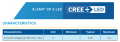
Semsvh, you looked at the wrong specs from an online seller who knows nothing about the parts he sells.
I looked at the Cree datasheet to see correct specs:
I looked at the Cree datasheet to see correct specs:
Attachments
-
 29.1 KB Views: 8
| Thread starter | Similar threads | Forum | Replies | Date |
|---|---|---|---|---|
| B | Powering LOTS of LED's with 9v batteries for longer | Power Electronics | 24 | |
|
|
Powering LED's from 2 (separate) sources | Power Electronics | 3 | |
| H | Powering led's, 9v battery not enough. | Power Electronics | 22 | |
| G | question on powering RGB LED's | Power Electronics | 3 | |
|
|
Powering ½W white LED's | Power Electronics | 24 |


