Powering LED from short AC pulses [rectifying and capacitor charging circuit]

Thread Starter

ommot

Joined Nov 21, 2008
9
Hi

I'm want to design a circuit that uses two cycles of an AC pulse to power a LED for approx 1 second.

The pulse is generated by a magnet flipping twice inside a coil, generating a 5V pulse.

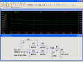
I was thinking of using a bridge rectifier to charge a capacitor which would be discharged by the LED.

Is this a good way of doing this? I'm not really sure the best way to arrange the LED and capacitor?

Could the rectifying be done by LEDs instead of normal diodes?

Thanks in advance

Tom
 

Wendy

Joined Mar 24, 2008
23,421
A bridge rectifier is 4 diodes, so I don't think LEDs would be that good. You could use schottkey diodes, which have a much smaller dropping voltage, as the bridge and a large cap/resistor/LED circuit.
 

Thread Starter

ommot

Joined Nov 21, 2008
9
Thanks Bill, that makes sense to use Schottky diodes for the bridge rectifier.

Could you tell me how I should arrange diode/capacitor and resistor?

Thanks
 

Norfindel

Joined Mar 6, 2008
326
It looks like the typical rectified ac to dc adapter, followed by a resistor and a led.

The bridge first to turn the AC into DC, then the capacitor to smooth the DC, then the resistor and the led.
 
Last edited:

Thread Starter

ommot

Joined Nov 21, 2008
9
Pretty much except that the AC signal will only be 2 cycles occuring once per second or so.

So the idea is that a capacitor is used to power the LED for 1 sec until the next pulse arrives.

Is there a way for to get the capacitor charged by the DC after the bridge and then to be discharged by the LED?

Thanks
 

Norfindel

Joined Mar 6, 2008
326
It will work regardless of the frequency.

When there's input voltage, it will charge tha capacitor and drive the led.

When there's no input voltage, the capacitor will drive the led.

The detail here, is that the capacitor must be big enough to drive the led while there's no input power, without the voltage dropping below the led's required minimum. If it drops too much, you're probably going to note that the led changes brightness (specially when the capacitor suddently charges).

I don't know where the input power is coming, but you must take into account that as the capacitor gets bigger, the charging current will get bigger also.
 

Thread Starter

ommot

Joined Nov 21, 2008
9
Thanks for the reply.

The input power is from a coil/magnet producing about 5V 25mA.

Is it possible to calculate the optimum capacitance for this type of circuit?

Also, should the capacitor, resistor and LED all be in series?

Thanks again
 

SgtWookie

Joined Jul 17, 2007
22,230
It's really not a very practical idea - unless perhaps the generator can put out a LOT of current for those two flips that can be stored in a large capacitor. But then, even using Schottky diodes, power will be wasted across the diodes.

I've attached an image of a simulation I whipped up in LTSpice. Notice how quickly the current in the LED drops off after the AC stops charging the cap.

If you download LTSpice/SwitcherCad from Linear Technology's website, you can experiment with the simulation.
[eta]
Since you say your generator produces 5v @ 25mA, change the Rser=10 of V1 to Rser=200.
Since R=E/I; 200 = 5v/25mA.

In order to provide 20mA to your LED, you will have to be spinning your generator constantly.
 

Attachments

Last edited:

Norfindel

Joined Mar 6, 2008
326
Yep, it's not practical. Too little input current.

If you want to know how to calculate the capacitance, take a look here: http://www.allaboutcircuits.com/vol_1/chpt_16/4.html

The procedure would be something like this:
* first you would need to find what resistor is required to drive the led at 3.6V (5v - 0,7 - 0,7 of the diodes)
* When the power is off, it's just an RC circuit, and you can calculate what capacitor you need to make it last 1 second (going from 3.6v to the led's Vf).
* Then, you would need to calculate what resistor you need to use to allow the capacitor to charge to a reasonable level from a 3.6v source in the short time the power is on. The maximum current draw, would be when the capacitor is fully discharged (works like a short circuit), and would be equal to 3.6v / the resistor you last calculated. If that current is higher than whatever device is supplying your power, you're screwed.

What are you trying to build, exactly?
 

Thread Starter

ommot

Joined Nov 21, 2008
9
I'm trying to build a device which uses one or more LEDs [up to 5 LEDs max] that are lit up by an object passing them approx 2-4 times per second.

My idea was to use a magnet inside the coil on the device which is flipped a magnet attached to the passing object to generate the power.

A capacitor is used to keep the LEDs lit or dimming from the initial pulse until the object passes again.

It is important the device is small and lightweight, and to that extent the brightness of the LEDs could be reduced in order to reduce the power requirements.

Could this be achieved without the bridge rectifier? If there where 2 or 4 LEDs could they be powered by the positive and negative parts of the cycle?

Thanks
 

SgtWookie

Joined Jul 17, 2007
22,230
No, you need the bridge. If LEDs are subjected to a PIV over around 5v, they will be destroyed.

Now you're saying that the object (or objects) will be passing 2-4 times per second. You'll get "blips" of light while the generator is being turned, but the light output will rapidly decay.

You may be surprised at how long some visible light continues to be emitted, but it will be at a very low level, and only be visible in reduced lighting conditions.
 

Norfindel

Joined Mar 6, 2008
326
Ok, that's not too many details to help very much. But take into account bycicle generators. The bycicle wheel doesn't spin too fast, but it's strong, so a mechanical device is used to make the generator spin really fast, and then you get something that can certainly light a led continuously.
If you can make use of something like that, i think it's the way to go.
 

Bernard

Joined Aug 7, 2008
5,784
What is the coil resistance ? Prbbably about 200Ω , so try two LED's head to toe,parallel with no resistor; should get a short blink. No cap to charge.
 

Thread Starter

ommot

Joined Nov 21, 2008
9
Bernard, the coil resistance is about 1000Ω.

will try the circuit out and let you know.

thanks

Nor, there can't be any mechanical connection between the two parts - but yes, if there was a lot more power could be drawn.

thanks


Thread Starter

ommot

Joined Nov 21, 2008
9
bernard,

it works well with both leds flashing, although one looks like its almost constantly on, barely flashing?

anyway to store some charge to keep them lit a bit longer?

thanks
 

Norfindel

Joined Mar 6, 2008
326
The problem is that you have very little power to start with. You can store whatever is there, but cannot make power from nothing.
What about using germanium diodes for the bridge rectifier? They have less voltage drop (0,3v), and that means brighter flashing. But try to not overload the coil, nor the leds.
You can probably use higher currents than 25ma, as it's not continuous.
Take a look at the datasheets to see what kind of current you can use for that duty cycle.

EDIT: what do you mean by both leds? how is your circuit right now?
 
Last edited:

Thread Starter

ommot

Joined Nov 21, 2008
9
I tried this suggestion

"What is the coil resistance ? Prbbably about 200Ω , so try two LED's head to toe,parallel with no resistor; should get a short blink. No cap to charge."

So the circuit I have is a coil of 1000Ω connected to two LEDs in parallel, arranged head to toe. So, no bridge or any other diodes except the LEDs. Works well, very bright flashes, almost too bright. One diode appears to stay lit longer than the other.

I'm using super bright white LEDs but could change these to lower power red LEDs - the white LED flashes are almost too bright - could some of that power be stored up instead?

Will this ultimate damage the LEDs?

Thanks
 

Norfindel

Joined Mar 6, 2008
326
It's difficult to say if it will damage the LEDs, or the coil. To know that, you should have the datasheets, and measure the peak current, and duty cycle. Watch for the peak inverse voltage of the LEDs, also.
If you don't know that, it's a matter of luck.
 

Thread Starter

ommot

Joined Nov 21, 2008
9
Thanks, I'll get hold of the datasheets for the LEDs

Any idea on how to hold some of the charge to keep them lit?

thanks
 
Top