power supply question

Thread Starter

yoamocuy

Joined Oct 7, 2009
84
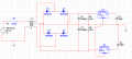
Hey, I've been working on a 15V power supply lately. I came up with the design shown in the attachment but when I hooked it up one of my 1000uF capacitors blew up after about 5 seconds. My transformer is rated for 12.6V rms and 3A, but its actual voltage is about 13.5 Vrms. I'm not sure what is wrong. My capacitor is rated for 50 V so it shouldn't be blowing up... Is there some obvious mistake with my design that would cause this to happen?
 

Attachments

SgtWookie

Joined Jul 17, 2007
22,230
You probably installed the capacitor with the polarity across it reversed; an easy mistake to make.

For the positive side, connect the negative cap lead to ground.
For the negative side, connect the negative cap lead to your negative bridge output; the positive side is connected to ground.

You really should have 0.33uF caps from the regulator inputs to ground, and 0.1uF caps from the output to ground, as close as possible to the regulators themselves.

Another possibility is getting the connections to the rectifier bridge wrong.
 

wayneh

Joined Sep 9, 2010
18,136
Probably a stupid question, but what's the reason for R1 and R2?

No relation to the cap blowing - I think Sarge has nailed that one - I'm just curious.
 

Thread Starter

yoamocuy

Joined Oct 7, 2009
84
Thanks for the tips, I'll check those things. 0.33uF instead of 1000uF? Don't I need to get the ripple down before putting it through the regulator?

I'm using the resistors so that I'll have a 3 second discharge time. They're acting as bleed resistors
 

bertus

Joined Apr 5, 2008
22,994
Hello,

The small capacitors must be ADDED to the circuit.
The 1000 uF is still needed.


The small capacitors prevent the regulators from oscillating.

Bertus
 

SgtWookie

Joined Jul 17, 2007
22,230
Sure, keep the cap sizes that you're using, but add the small caps as close as possible to the regulator.

Without them, the regulators may oscillate at high frequency. The larger caps may have an ESR that is too high, or have to be placed too far away to keep the oscillations under control.
 

eblc1388

Joined Nov 28, 2008
1,542
I took the advise literally.

I often soldered the 0.33uF and 0.1uF capacitors directly across the pins of the regulator, close to epoxy body, using smd parts.

Don't seem to be getting any problems so far.
 
Top