Power On Latched Relay Driver

Thread Starter

STGMavrick

Joined Jan 21, 2009
13
Hey guys,

I humbly ask for your help. Its been a long time since i've designed circuits as my profession changed to PLC based controls. So i'm kind of stumped as to how to accomplish my small project.

Currently i'm using a 24v micrologix PLC to activate a solenoid. Using a PLC is what i know, so it was relatively simple and effective. I'm looking to perfect it to keep the system simple. An expensive PLC adds bulk and is expensive to replace if it gets damaged.

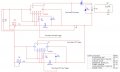
The ultimate goal is to use a 12v DC power source to activate a 12v relay which the N.O. contacts will be used to drive a 12v solenoid.

Functional Description:

A rocker switch (S1) is used to "set" the system. If this switch is not closed, the system will not operate. S1 has both a N.O. and a N.C. terminal. I've referred to it below using the N.O. Terminal.

On power up once S1 has closed, the system is ready to energize the relay. A momentary switch(S2) will close the relay.
Once S2 has been closed, the relay will stay energized for an adjustable 0-X seconds and then re open.
Once the relay has been energized, opening and closing S2 again has no effect on the circuit.
Once the relay has been energized and reopened it cannot be energized again until S1 has been opened and closed and after an adjustable time of 0 - 30 minutes. After the 30 minutes, closing S2 will energize the relay.
Disconnecting the power will reset the circuit.

I've looked at a few 555 timer circuits and i just dont have the know how anymore to modify it to meet my functional requirements.

Any help would be greatly appreciated. If more input from me is needed, i will most definately try my best to answer your questions.

Thank you for your time,

Marshall
 
Last edited:

Thread Starter

STGMavrick

Joined Jan 21, 2009
13
I've added my unfinished design. I hope that someone might be able to fill in the blanks of my functional description.

I appreciate any help i can get.

Thanks,
Marshall
 

Attachments

mik3

Joined Feb 4, 2008
4,843
First, I think the volume a small PLC occupies is less than the pcb you are going to build. Also, PLCs are more reliable than the 555s and you can change their function easily.
What is more, I don't think PLCs brake down easily. A good design for relay output PLCs is not to use the relay in the PLC to drive the load but drive another relay and connect the load to the external relay. Thus if a short occurs only the external relay will be destroyed.
Anyway, in your circuit you have to put a 1K resistor in series with the pots because if you turn the pot until its hits zero ohms then the 555 is gone. Also, if the relay is 12V you don't need D1 there. It would be better to connect it in parallel with the relay coil (with its cathode facing the positive pole of the battery) the to avoid any arcing across the relay contacts.
 

Thread Starter

STGMavrick

Joined Jan 21, 2009
13
First, I think the volume a small PLC occupies is less than the pcb you are going to build. Also, PLCs are more reliable than the 555s and you can change their function easily.
What is more, I don't think PLCs brake down easily. A good design for relay output PLCs is not to use the relay in the PLC to drive the load but drive another relay and connect the load to the external relay. Thus if a short occurs only the external relay will be destroyed.
Anyway, in your circuit you have to put a 1K resistor in series with the pots because if you turn the pot until its hits zero ohms then the 555 is gone. Also, if the relay is 12V you don't need D1 there. It would be better to connect it in parallel with the relay coil (with its cathode facing the positive pole of the battery) the to avoid any arcing across the relay contacts.
I realize what you are saying. I'm an allen bradley man myself, i've got a few around my office i can test with, but nothing i can "keep". A small circuit only costs a couple bucks. A small 24v plc can cost a couple hundred.

I was going to use a 12v relay, but isnt the output on a 555 lower than the Vcc? at 12v , the out put would be near 10v.

Thanks for the info on the 1k resistor, i didnt know that.
 

mik3

Joined Feb 4, 2008
4,843
Yes, the output will be lower than 12V but I think it still can pull in. Have you considered how much current the relay coil needs? A 555 output can provide only 200mA.
 

Thread Starter

STGMavrick

Joined Jan 21, 2009
13
Yes, the output will be lower than 12V but I think it still can pull in. Have you considered how much current the relay coil needs? A 555 output can provide only 200mA.
Yeah, the relay i'm using is a 12v, has a coil rating of 75mA and coil pull in is 9.6v min
 

mik3

Joined Feb 4, 2008
4,843
It will be fine, just connect it to the output of the 555 without the diode. Also, don't forget the diode (its cathode facing the 555 output) in parallel with the relay coil.
 

Thread Starter

STGMavrick

Joined Jan 21, 2009
13
I decided to switch the relay driving to using an NPN transistor. I've attached the updated schematic.

So i'm left with 4 inputs / outputs that i cannot figure out how to interface together. I'd like to use just one momentary contact to control the circuit.

Press the button: Time on for a couple seconds to give the solenoid enough time to do what it needs to do. Once it goes back to the "off" state, i'd like to use the second 555 circuit to time off for up to 30 minutes. Once the preset time has passed, you can use the momentary again to energize the solenoid. Rinse and repeat.
 

Attachments

mik3

Joined Feb 4, 2008
4,843
Connect to the output of the second 555 a transistor like in the first 555 but instead of using a relay as the load use a 1K resistor (note that you don't need the diode here). Then disconnect the reset pin of the first 555 from Vcc and connect to the collector of the second transistor you added.
Operation:

When the output of the second 555 is low the first 555 will be able to work (reset pin high). However, when you trigger the second 555, its output will go high, the transistor will turn on and pull reset pin to ground. Thus the first 555 won't be able to work until the second 555 has count the preset time.
 

Thread Starter

STGMavrick

Joined Jan 21, 2009
13
Connect to the output of the second 555 a transistor like in the first 555 but instead of using a relay as the load use a 1K resistor (note that you don't need the diode here). Then disconnect the reset pin of the first 555 from Vcc and connect to the collector of the second transistor you added.
Operation:

When the output of the second 555 is low the first 555 will be able to work (reset pin high). However, when you trigger the second 555, its output will go high, the transistor will turn on and pull reset pin to ground. Thus the first 555 won't be able to work until the second 555 has count the preset time.
Ok, i've taken this a step further, however here's the new operation thus far.

When the output of U1(first 555) is high the reset on U3(second 555) is pulled to ground preventing it from timing. This allows the Time ON to complete before U2 starts it off delay timing.

I dont know if i'm thinking of too many things within this circuit at once or not, but i'm stuck figuring out how to tie in the triggers to U1 and U3 to my 2 sets of contacts.

S3 is my arming. U3's timing should not be affected by this switch, however U1 should not be able to start a time until S3 has been closed. J1 is my momentary pushbutton to "fire" the solenoid. I'm thinking to wire these 2 switches in series between the trigger of U1 and ground; However, what will i do with my last trigger input of U3? Somehow completing timing on U1 should trigger U3 to start timing after U1's output has gone from high back to low.

Attached is the updated circuit. I should also note that J1 is a push to close switch. The image displays the last state of a switch during the test.
 

Attachments

Last edited:

mik3

Joined Feb 4, 2008
4,843
First some corrections:

-Connect the reset of U3 to the collector of Q3 and the top of R9 to Vcc
-Connect the reset of U1 to the collector of Q2 and the top of R8 to Vcc

To achieve the thing with S3 and J1 connect S3 between the bottom side of R1 and ground and J1 between pin 2 of U1 and Vcc. Also, remove the wire going from the bottom of R1 to Vcc.
 

Thread Starter

STGMavrick

Joined Jan 21, 2009
13
Ok, updated with your recommendations.

What should i do with trigger pin on U3. I thought pulling it to ground would work, however once the OFF cycle has completed, it shouldnt count again until U1 has been activated.


I really do appreciate all of the help you've given my mik3.
 

Attachments

Thread Starter

STGMavrick

Joined Jan 21, 2009
13
Updated with your corrections.

I've got one last issue. Somehow the output of U1 needs to trigger U3 after it goes from High to Low. I've been playing around all day and i cant figure out how to do it.

Also, i'm having a problem with the circuit as it is, the output of U3 is staying high on power up and sustains.
 
Last edited:

mik3

Joined Feb 4, 2008
4,843
J1 has to be connected between Vcc and R1 (not between R1 and trigger).

To achieve triggering of U3 when U1 counts its preset time use a RS latch or another 555 as a bistable.
 

mik3

Joined Feb 4, 2008
4,843
But you haven't make the correction yet. Disconnect J1 from where it is and connect it between the top of R1 and 12V (remember to remove the wire from the top of R1 to 12V). Then connect the top of R1 to trigger pin of U1.

To trigger U3 when U1 finishes timing use a negative edge triggered flip flop. Connect its S input to the output of U1 and its Q to the trigger of U3.
 

Thread Starter

STGMavrick

Joined Jan 21, 2009
13
I had it that way, however i changed it back because when i try to simulate the circuit, it immediately fails. I'm using Electronics workbench and i cant decypher the errors. From what i can tell, it has something to do with Q3's emitter.

EDIT: Should there be a resistor between U1 and the base pin of Q3?
 

Attachments

Last edited:

mik3

Joined Feb 4, 2008
4,843
I had it that way, however i changed it back because when i try to simulate the circuit, it immediately fails. I'm using Electronics workbench and i cant decypher the errors. From what i can tell, it has something to do with Q3's emitter.

EDIT: Should there be a resistor between U1 and the base pin of Q3?
Yes, put a 2.2K resistor between the base of Q3 and output of U1. Do the same for Q2 and U3.

I think that Multisim doesn't have a RS latch in its database and you won't be able to simulate it. Can you find a RS latch?
 

Thread Starter

STGMavrick

Joined Jan 21, 2009
13
Yes, put a 2.2K resistor between the base of Q3 and output of U1. Do the same for Q2 and U3.

I think that Multisim doesn't have a RS latch in its database and you won't be able to simulate it. Can you find a RS latch?
I've got a 74LS279, its a quad sr latch. Is this adequate?
for a negative edge triggered latch, shouldnt there be one with a clock(C) input?

I've also replaced U1 and U3 with a 556 dual timer IC.

Also, i should note that simulating the circuit as is at power up the output of U1A stays 12v. J1 and S3 are open.
 
Last edited:
Top