Potentiometer made a liar out of me. trouble shooting help.

Thread Starter

Teljkon

Joined Jan 24, 2019
267
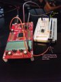
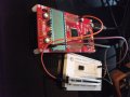
So this Udemy class I am doing. Requires a project with a potentiometer. Point being I think the dam thing is broken. The MSP430 launch pad that the class requires also wont show the registers but that is a whole different problem. As far as I know. so the circuit is rather simple. I take power from a pin marked 3v3 then send it to the bread board threw a 470 ohm resistor then to ground finally threw the potentiometer to pin 9.2 if the micro controller reads above 1.65v led comes on.

Now basically what is happening is light only comes on after the ground is removed from the circuit. The whole circuit reads roughly 3.3v, if you wan't to be precise 3.28 to 3.32 with the ground removed. here is the odd thing I had this cuircuit working the other day and the high side was flipped?? The other odd thing is that if the ground is in i can't get a reading after the resistor ( this may be my inexperience with electricity showing).

So what is the rub here is this a classic bad potentiometer or what? An, why wouldn't i be able to get a reading after the resistor when the ground is connected. Is there any way some one would suggest testing the potentiometer without it being part of this circuit. Ignore the small black chip its there just so i don't bend the leads when I transport it from work to home.
 

Attachments

WBahn

Joined Mar 31, 2012
30,045
Please don't make people try to figure out your circuit based on pictures, especially ones where we can't see EXACTLY what is connected to what is connected to where.

Provide a schematic of how you (intended) to connect everything.

This makes no sense:

"I take power from a pin marked 3v3 then send it to the bread board threw a 470 ohm resistor then to ground finally threw the potentiometer "

It sounds like you have the resistor between power and ground. So how can it THEN go through (not threw) the potentiometer?

Again, provide a schematic.
 

Thread Starter

Teljkon

Joined Jan 24, 2019
267
other than hand draw a schematic i don't have anything to do that is that what you want? or perhaps i can draw it on the picture.
 

BR-549

Joined Sep 22, 2013
4,928
I can't follow what you are saying. What are you trying to adjust with the pot? Power for a chip, or to turn a light on?
 

Thread Starter

Teljkon

Joined Jan 24, 2019
267
power going to the chip, keep in mind this is not my cuircuit its the instructors. Also is this not a massive picture for you guys like it is for me? The real point is my potentiometer seems broken how could I confirm this?


Attachments

BR-549

Joined Sep 22, 2013
4,928
Are you sure that this is for powering the chip? Could it instead, be an adjustable voltage input to the chip, and not for power?

Didn't the instructions give you a schematic?
 

Thread Starter

Teljkon

Joined Jan 24, 2019
267
Are you sure that this is for powering the chip? Could it instead, be an adjustable voltage input to the chip, and not for power?

Didn't the instructions give you a schematic?
I guess it's not powering the whole chip it powers the pin that reads the voltage, so yes powering the chip. Any way I did this at work today real quick hope it helps.

cuircuit bad potent.jpg
 

BR-549

Joined Sep 22, 2013
4,928
Not sure what a Udemy class is.......does it have anything to do with electronics?

Have you ever used a pot before? Do you see 3 terminals on the pot?
 

Thread Starter

Teljkon

Joined Jan 24, 2019
267
both upper terminals on the slide pot are on the same bar in the bread board. I have only used a pot in this class. Udemy classes are cheap online courses in many subjects 15$ or so. Yes it has to do with electronics this one is on micro controllers this specific section is on using analog to digital converters. I actually have a voltmeter that reads ohms how would you go about testing the potentiometer?
 

BR-549

Joined Sep 22, 2013
4,928
To test it, just pull it off the board. Identify the slider terminal and connect meter lead ground to it.

Set ohmmeter to appropriate scale for pot. Zero meter if necessary.

Connect red meter lead to any end terminal......adjust slider thru range and watch meter.

Verify the range, but pay attention to the smoothness of the meter movement.

Or the bar graph on a digital meter.

Both ends should test the same.

Does this make sense to you?

Now you can figure how it goes in the circuit.
 
Last edited:

Thread Starter

Teljkon

Joined Jan 24, 2019
267
Ok, I think this makes sense one of the terminals on the meter is the slide terminal basically the one that connects to the action side of the circuit. Now I should probably power it on the third terminal right?
 

crutschow

Joined Mar 14, 2008
34,407
If you want to sample the 3.3V from the supply with a pot adjustment, then the 470Ω resistor needs to be connected from the (+) terminal of the power supply to the "pin sampling voltage" with the pot connected as shown (wiper connected to one side of the pot).

A likely better way to connect the pot would be to connect one end to ground, the other end to +3.3V, and the wiper to the "pin sampling voltage".
 

BR-549

Joined Sep 22, 2013
4,928
No. NO.

When you pull it off the board........it's not connected to anything......right?

Why are you talking about powering anything up?

Have you had any electronics training?

Have you ever used a meter?

Did this course require any previous courses or qualifications?.

This is not good.
 

Thread Starter

Teljkon

Joined Jan 24, 2019
267
No. NO.

When you pull it off the board........it's not connected to anything......right?

Why are you talking about powering anything up?

Have you had any electronics training?

Have you ever used a meter?

Did this course require any previous courses or qualifications?.

This is not good.
Ok correct if I remove it from the board there is no power to it. If I isolate it on it's own rail there is also no power going to it. How would i get a reading without any power going to the pot? Will the motion on the pot cause a current of some kind?


Sorry zero electronics skill never played with any at all until now. Also why is this not good its ok the world will not end because i don't have a great understanding of how a potentiometer works. Thats why I am doing this though to learn.
 
Last edited:

BR-549

Joined Sep 22, 2013
4,928
There is a mis-understanding here. This is the homework forum. We can't give you answers here.

And things like this......you can't jump in at the middle.

You have to start at the beginning. You can't learn it backwards.

This is for students who have a particular homework problem.

One needs to understand voltage, current and resistance......to understand how to use a meter.

I shall retire. Good Luck.
 
Top