
Hi,
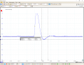
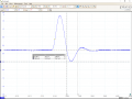
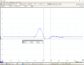
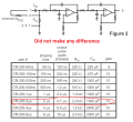
I am designing a Gaussian shaping amplifier based on Cremat-200 series shaping amplifier module. I always have a fixed 1-1.2 us duration voltage spike looking signal at the input and I want to transform that signal into roughly 10 us duration Gaussian shape signal at the output. I am using 2 stage Sallen-key filters for that (all resistors are 10k, all capacitors are 220 pF). Problem arises when after each stage I see a stronger pole in my signal (check attachments) that I have to somehow eliminate. I tried to make a PZ circuit just like they suggest in the Cremat-200 module datasheet, even tried to different pot values (10k and 100k) and capacitors (100 pF to 1 nF) but that made no difference. You can see all the timings and the amplitudes of the pole in the attachments. Can you please give me exact guidelines how do I make the PZ circuit? I did my research online, but all this PZ theory only looks good in terms of math. It is really difficult to adapt all that complex math to real life scenario RC network. Thank you in advance.
I am designing a Gaussian shaping amplifier based on Cremat-200 series shaping amplifier module. I always have a fixed 1-1.2 us duration voltage spike looking signal at the input and I want to transform that signal into roughly 10 us duration Gaussian shape signal at the output. I am using 2 stage Sallen-key filters for that (all resistors are 10k, all capacitors are 220 pF). Problem arises when after each stage I see a stronger pole in my signal (check attachments) that I have to somehow eliminate. I tried to make a PZ circuit just like they suggest in the Cremat-200 module datasheet, even tried to different pot values (10k and 100k) and capacitors (100 pF to 1 nF) but that made no difference. You can see all the timings and the amplitudes of the pole in the attachments. Can you please give me exact guidelines how do I make the PZ circuit? I did my research online, but all this PZ theory only looks good in terms of math. It is really difficult to adapt all that complex math to real life scenario RC network. Thank you in advance.
Attachments
-
 72.9 KB Views: 5
 -
 59 KB Views: 5
 -
 70.2 KB Views: 8
 -
 58.6 KB Views: 9


