Please help out with 7 segments circuit

Thread Starter

tqcenter2002

Joined Jun 13, 2011
1
Hi All,

I am new to the forum and I would be happy to participate.
I have been trying to put up a 7 Segment circuit with Multisim using a 4511 referenced by http://www.rficdesign.com/img/05318.png


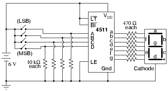
And with no luck at all. I could not make the 7 segment light at all - I only got blinks.
For those who works with Multisim - How can I unhide the VCC VDD pins in the 4511 (or any other chip)?

Thanks in advance,
Eric.
 

mbohuntr

Joined Apr 6, 2009
446
I didn't have much luck with it either. I got the 1st and second bit ok, but the rest is screwy. Been awhile since I took digital, so it's probably something simple. I tried all different configurations for the inverted pins. Try the sample circuits for a schematic, I know there's one in there.
 

Attachments

Last edited:

djsfantasi

Joined Apr 11, 2010
9,163
Where did you get the value of 470Ω for your resistors before the 7 segment display?

The 4711 can source a maximum of 25ma; at that current, 11.75 volts will be dropped by the resistors. There will unlikely be enough voltage/current to drive the LEDs in the segment.

You also need the specifications of the segment current draw and rated voltage. Then, from those values, the Rd value can be calculated as follows: Rd = (Vss - Vled)/Iled
 

SgtWookie

Joined Jul 17, 2007
22,230
There does not appear to be anything wrong with your schematic diagram.

I am not familiar with Multisim.
Cadsoft Eagle by default hides the power pins on IC's in the schematic; you have to know the name of the pin (whether +V,Vcc, Vdd, GND, Vee, Vss, -V) in order to have a same-named node somewhere in the schematic for the program to automatically connect it.

For your simulation, try using a 5v to 12v source with a node name of Vdd, and also have an 0v source named Vss and GND. You will probably have to have a GND symbol in your schematic somewhere in order for the simulation to run.

You can also try to see if the fault may lie in the 7-segment display portion by grounding the cathode sides of the resistors. If you see current flowing through the resistors, then the 7-segment portion is not working properly.

You can also try connecting the LT\ input to GND to use the "lamp test" function; all 7 segments should be lit.
 
Top