PIC16F88 problem controlling hbridge

Thread Starter

aGpLT

Joined Jan 21, 2010
128
After experimenting with the IR2110 a bit in simulation, found some interesting things.

It is not shown in the datasheet, but in the simulation when power is first applied, very heavy initial currents flow from the logic inputs through to ground - I'm talking hundreds of Amperes. I don't know why this is.

Anyway, if SD is raised, it "forgets" what state it's inputs were previously.

So, for starters, you raise SD to make sure it's turned off.

Then you go around and turn off all of the PIC outputs.

Then you lower SD, and wait a few microseconds to make sure it "took".

Then you can turn on the parts of the bridge that you want.
Heh i don't get it at all why is it needed for what reason....

so i tested your program and get on all LIN/HIN 0.2 - 0.4 V ! :D without bridge i measured all RB0-RB4 and program was working normally (like last program).
 

SgtWookie

Joined Jul 17, 2007
22,230
OK, so I think you are having a problem when you apply a load to your H-bridge.

You need to show how you have constructed the board, and how you have the PIC wired to it.
 

Thread Starter

aGpLT

Joined Jan 21, 2010
128
OK, so I think you are having a problem when you apply a load to your H-bridge.

You need to show how you have constructed the board, and how you have the PIC wired to it.
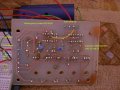
Sorry for quite low quality of pics. and in second pic is mistake instead of RLIN must be RHIN. :>

Yeah that's right something wrong with load. When i disconnected motor, measured capacitors, it charges to 10.2V transistor VT2 Vgs goes to 10.2V others Vgs = 0. yeah i know its left side low (in electric scheme) , but it doesn't matter it's just words, concept is same :> Also measured LHIN (slowly growing till 5V and nothing more after that), i think other transistor should open either like VT3 (LHIN) but it don't. on the load i get always 5V one side and other 0V, doesn't it supposed to gwor like LHIN ?

I putted two leds and connected them same ground via resistor to ground and anodes to load pins. When i measured again VT3 and it's growing slowly. Program is working correctly, just its quite long process to grow till 5V w8 some time (quite long) when going low (slowly slowly the same as growing) and it goes same to another side.
 

Attachments

Last edited:

SgtWookie

Joined Jul 17, 2007
22,230
Oh my gosh, that's terrible! :(

You have long loopy wires running all over the place (and each other) and you don't have a cap across the PICs' power/ground pins.

One BIG problem that you will have is the inductance in the wiring, particularly when you have a large inductive load. This will make your grounds "ring" like the dickens, and is probably why you are blowing out IR2110 IC's.

A straight piece of wire 10mm long has an inductance of about 15nH at 10MHz. So, if you have 150mm of wire going from the power supply to your board, that's 150mm x 2 (power, ground) x (15nH/10) = 450nH inductance. It adds up VERY quickly, and causes big problems with high frequency signals. If the wires are curved or looped, the inductance increases quite a bit.

You might say, "Wait a minute - I am using pretty low frequencies in this project"

You need to understand that square waves (which is what digital logic signals are) are composed of the fundamental frequency/frequencies, plus ALL of the odd harmonics of the fundamental frequency/frequencies.

The picture in this Wiki article helps a great deal to illustrate what I'm talking about:
http://en.wikipedia.org/wiki/Square_wave
Click this link to see the image animate:
http://upload.wikimedia.org/wikipedia/commons/f/f8/SquareWave.gif

The red trace is a perfect square wave; you can see how the green trace starts off with just the fundamental frequency as a sine wave; then proceeds to add up to the 11th odd harmonic. This is why digital signals require a much higher bandwidth than analog signals do.

High frequencies and long, loopy wiring do not go along together well at all.
 

Thread Starter

aGpLT

Joined Jan 21, 2010
128
Oh my gosh, that's terrible! :(

You have long loopy wires running all over the place (and each other) and you don't have a cap across the PICs' power/ground pins.

One BIG problem that you will have is the inductance in the wiring, particularly when you have a large inductive load. This will make your grounds "ring" like the dickens, and is probably why you are blowing out IR2110 IC's.

A straight piece of wire 10mm long has an inductance of about 15nH at 10MHz. So, if you have 150mm of wire going from the power supply to your board, that's 150mm x 2 (power, ground) x (15nH/10) = 450nH inductance. It adds up VERY quickly, and causes big problems with high frequency signals. If the wires are curved or looped, the inductance increases quite a bit.

You might say, "Wait a minute - I am using pretty low frequencies in this project"

You need to understand that square waves (which is what digital logic signals are) are composed of the fundamental frequency/frequencies, plus ALL of the odd harmonics of the fundamental frequency/frequencies.

The picture in this Wiki article helps a great deal to illustrate what I'm talking about:
http://en.wikipedia.org/wiki/Square_wave
Click this link to see the image animate:
http://upload.wikimedia.org/wikipedia/commons/f/f8/SquareWave.gif

The red trace is a perfect square wave; you can see how the green trace starts off with just the fundamental frequency as a sine wave; then proceeds to add up to the 11th odd harmonic. This is why digital signals require a much higher bandwidth than analog signals do.

High frequencies and long, loopy wiring do not go along together well at all.
so many mistakes. :| sorry for bothering with total nab which even don't know fundamentals.... studied for 3 years and learnt nothing...

So how i could correct it ? yeah i know short wires, but i can only shorten one side wires because another side will be same... i don't have any idea at all how to connect without using several long wires...
 

SgtWookie

Joined Jul 17, 2007
22,230
We were all "n00bs" once upon a time. That is why I am trying hard to be patient, and explain things.

The important thing here is that we learn from our mistakes, and try to not repeat them in the future.

I made a big mistake, as I didn't ask about your layout before. :(

You posted an image of a board which I had quickly glanced at days ago, but it didn't register in my little brain that your PIC was on a completely separate breadboard.

I have to leave very shortly, but will return after awhile.

You really need a new board layout, with the PIC onboard and located close to the IR2110.
 

Thread Starter

aGpLT

Joined Jan 21, 2010
128
We were all "n00bs" once upon a time. That is why I am trying hard to be patient, and explain things.

The important thing here is that we learn from our mistakes, and try to not repeat them in the future.

I made a big mistake, as I didn't ask about your layout before. :(

You posted an image of a board which I had quickly glanced at days ago, but it didn't register in my little brain that your PIC was on a completely separate breadboard.

I have to leave very shortly, but will return after awhile.

You really need a new board layout, with the PIC onboard and located close to the IR2110.
:|for my project i need 3 of these controllers for one pic (also shift registers, to get enough pins...) still i don't know how to work with them, to write such program to send information... i think i really won't graduate this year :) because i only have one week to make working model.

If i need everything on one board. i don't know... its taking so much time, to draw one, etch, drill, solder....
 

SgtWookie

Joined Jul 17, 2007
22,230
I'm pretty certain that you have fried the IR2110's yet again. The PIC's outputs coming up OK by themselves, but not going above 0.2v-0.3v when connected to the IR2110's indicates that they are causing a problem.

You may have also fried one or more of the MOSFETs.

While I am gone, why don't you try replacing the IR2110's and testing each of your MOSFETs to make certain that they are OK:
1) Measure resistance from gate to source, and gate to drain. It should measure open circuit. If not, it is shorted.

2) Connect the gate to the source using a jumper. Using a meter set to diode test, the MOSFET should test open one way, and about 500mV to 700mV the other way. If not, it is defective.

3) Connect a 10v to 15v power source between the gate and source terminals. You should measure nearly zero resistance between the drain and source terminals.
 

Thread Starter

aGpLT

Joined Jan 21, 2010
128
I'm pretty certain that you have fried the IR2110's yet again. The PIC's outputs coming up OK by themselves, but not going above 0.2v-0.3v when connected to the IR2110's indicates that they are causing a problem.

You may have also fried one or more of the MOSFETs.

While I am gone, why don't you try replacing the IR2110's and testing each of your MOSFETs to make certain that they are OK:
1) Measure resistance from gate to source, and gate to drain. It should measure open circuit. If not, it is shorted.

2) Connect the gate to the source using a jumper. Using a meter set to diode test, the MOSFET should test open one way, and about 500mV to 700mV the other way. If not, it is defective.

3) Connect a 10v to 15v power source between the gate and source terminals. You should measure nearly zero resistance between the drain and source terminals.
About IR2110 i don't have any, because local shops don't have this component now. About MOSFET's:

done second test:

one of four beeped when negative on drain positive on source.

Maybe i think i need to drop this one for now, because off time, maybe i need just to choose correct P channel MOSFET's and do h-bridge with them, several pull-down gate resistors, some control transistors (left/right) and that's all. what you think ?
 
Last edited:

SgtWookie

Joined Jul 17, 2007
22,230
Your circuit will be more complex due to the P-ch MOSFETs and your supply voltage.

It can be done that way, but the benefit is questionable. Also, in order to have a similar Rds(on) as an N-ch MOSFET, you wind up with a penalty of a higher gate charge.
 

Thread Starter

aGpLT

Joined Jan 21, 2010
128
what about other drivers ? or it doesn't matter ? is there anything to do it faster and simpler way to make this using only two uC pins ? :> this one i will not drop because it's principles, but for now i don't have enough time to analyze everything to fundamentals, with your help i started liking electronic i found it a lot more interesting when you are trying to understand how it works, it's like mania, but for now i need only end this project, after that study myself from beginning ! long trip... i get it much more interesting if you try to understand not only theoretically but in practice.

--------------------------------------------------------------
Your circuit will be more complex due to the P-ch MOSFETs and your supply voltage.

It can be done that way, but the benefit is questionable. Also, in order to have a similar Rds(on) as an N-ch MOSFET, you wind up with a penalty of a higher gate charge.
http://www.armory.com/~rstevew/Public/Motors/H-Bridges/Blanchard/figure-1.htm this one doesn't seem quite hard, but to find require pmos its another talk. And what about my supply voltage ?
 
Last edited:

R!f@@

Joined Apr 2, 2009
10,007
I did work with L298 and I too have the same problem.
Either the IC or the motor get's hot.
I wonder what we are doing wrong?
 

Thread Starter

aGpLT

Joined Jan 21, 2010
128
I did work with L298 and I too have the same problem.
Either the IC or the motor get's hot.
I wonder what we are doing wrong?
i Just tryed once more, and now using PWM i get quite annoying noise from motor :))) i measured output from L298 and get 1A with 4,2V what i want but... Mr. Sqt said: "If you really want to use the L298, you should consider operating it directly from 12v, and using the L297 IC to control the motor current."
 
Top