pic16f628a working with external oscillator

Thread Starter

viva_unix

Joined Apr 24, 2010
26
hello!
i have an application that works. Looks like that:

Rich (BB code):
#include <pic.h>
#include <htc.h>
 
#define _XTAL_FREQ 4000000
__CONFIG(MCLRDIS & BORDIS & INTIO & PWRTEN);
 
#define SRCLK   RB1
#define SRDAT   RB2
#define SRLAT   RB3
static int iBinary;
void OutPORT(unsigned char data);
void main()
{
    CMCON = 0x07;
    TRISB = 0x00;
    PORTB = 0x00;
 iBinary = 0x01;
    while(1)
    {
        OutPORT( iBinary );
        __delay_ms( 0x8F );
        OutPORT( iBinary );
        __delay_ms( 0x8F );
  if( ++iBinary == 0x0100 )
  {
   iBinary = 0x01;
  }
    }
}
void OutPORT(unsigned char data) 
{ 
   unsigned char bits; 
   for (bits = 0x80; bits != 0; bits >>= 1) 
   { 
      if ((bits & data) == bits)           
      {
         SRDAT = 1; 
      }
      else 
      {
         SRDAT = 0; 
      }
      SRCLK = 1;                             
      SRCLK = 0; 
   }
    SRLAT = 1;                                
    SRLAT = 0;
}
if I change top lines to:

Rich (BB code):
#define _XTAL_FREQ 8000000
__CONFIG(MCLRDIS & BORDIS & INTIO & PWRTEN & HS);
it stops working.

I do add an external oscillator for 8MHz. Is there a rule of how attach it? Should it use some resistor or capacitor? Am I missing something else?

Thank you!
 

AlexR

Joined Jan 16, 2008
732
A circuit diagram would help us see just what you are doing.
Are you adding an oscillator module or just a crystal? If its just a crystal do you have got capacitors going from each side of the crystal to earth (15pf-22pF is normal)?
Have you read the PIC16F628A data sheet? If not do so as it has a section on how to use oscillators and crystals.
 

John P

Joined Oct 14, 2008
2,068
Have you done everything according to section 14.2 of the manual?

And no, it doesn't seem as if you need any additional components when using an external clock.
 

Thread Starter

viva_unix

Joined Apr 24, 2010
26
A circuit diagram would help us see just what you are doing.
Are you adding an oscillator module or just a crystal? If its just a crystal do you have got capacitors going from each side of the crystal to earth (15pf-22pF is normal)?
Have you read the PIC16F628A data sheet? If not do so as it has a section on how to use oscillators and crystals.
I am trying to connect PIC16F628A to 74HC595 shift register that powers the lights.
Here is the video of how it runs. Can someone explaine me why does it stops sometimes? This happens without external crystal, with crystall I do not see lights at all! :(

http://www.youtube.com/watch?v=yLivQD4fmU4

currently my application looks like that:
Rich (BB code):
#include <htc.h>
#define _XTAL_FREQ 4000000
__CONFIG(MCLRDIS & BORDIS & INTIO & PWRTEN & WDTEN);
 
#define SRCLK   RB1
#define SRDAT   RB2
#define SRLAT   RB3
void OutPORT(unsigned char data);
void main()
{
    CMCON = 0x07;
    TRISB = 0x00;
    PORTB = 0x00;
    while(1)
    {
        OutPORT( 0x00 );
        __delay_ms( 0x8F );
        OutPORT( 0xFF );
        __delay_ms( 0x8F );
  CLRWDT();
    }
}
void OutPORT(unsigned char data) 
{ 
   unsigned char bits; 
   for (bits = 0x80; bits != 0; bits >>= 1) 
   { 
      if ((bits & data) == bits)           
      {
         SRDAT = 1; 
      }
      else 
      {
         SRDAT = 0; 
      }
      SRCLK = 1;                             
      SRCLK = 0; 
   }
    SRLAT = 1;                                
    SRLAT = 0;
}
interesting that it happened not constantly. It might run for 10 minutes fine than start doing some wired things... :(

I will take a look at manual for 16f628a. I do have it in pdf.

Thank you!

P.S. I am trying to add 8 MHz Quartz Crystal HC-49/U4H

P.S.S. I do also have SG531P, is it better?
 

AlexR

Joined Jan 16, 2008
732
Like a said, post a circuit so we can see any glaring errors.
Eg. Do you have your supply pins bypassed?, have you got the crystal capacitors connected correctly?

Also when you connect the crystal do you change your code from
"#define _XTAL_FREQ 4000000"
to
"#define _XTAL_FREQ 8000000"
and recompile the code?

If you don't then all your timing loops will be wrong and the circuit may be working but the LEDs would be flashing too fast to see them!
 

rjenkins

Joined Nov 6, 2005
1,013
Simply using the breadboard may be a problem due to the connecting wire lengths.

Do you have a decoupling capacitor DIRECTLY across the power pins on the PIC and the other ICs?

Any connections for grounds or high frequency signals should be as short as possible, eg. use bits of bent tinned copper wire or component lead to bridge a 0V/ground pin to the adjacent ground bus, not a loop of wire up in the air.

The total length of the wires and leads for each crystal connection should not be more that about 20mm or so. Ideally plug the crystal leads directly in the rows from the PIC osc pins and add load caps (10pF should do) from the same two rows back to a PIC ground pin.
 

Thread Starter

viva_unix

Joined Apr 24, 2010
26
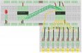
Here is my diagram in attachment. I have problem:

1. the crystall does not work when I add it.
2. the circuit works somewhat funny. Please take a look at youtube video I have uploaded.

Open for any suggestions and recommendations.
Thank you!
 

Attachments

AlexR

Joined Jan 16, 2008
732
Add bypass capacitors (100nF) from PIC Vdd pin(14) to earth and from the 74XXX chip Vdd/Vcc pin(16) to earth.

I also like to add a 100nF capacitor across each supply rails on the breadboard and a 220uF or 470uF electrolytic connected across where power comes into the breadboard.

When you connect the crystal to the PIC (pins 15 and 16) make sure you also connect 22pF capacitors from each of those pins to earth.
 

Thread Starter

viva_unix

Joined Apr 24, 2010
26
Add bypass capacitors (100nF) from PIC Vdd pin(14) to earth and from the 74XXX chip Vdd/Vcc pin(16) to earth.

I also like to add a 100nF capacitor across each supply rails on the breadboard and a 220uF or 470uF electrolytic connected across where power comes into the breadboard.

When you connect the crystal to the PIC (pins 15 and 16) make sure you also connect 22pF capacitors from each of those pins to earth.
OK. I will try to do it right after I get home today.
How important those numbers? I might not have the exact capacitors you are talking about... :(

Thank you!
 

AlexR

Joined Jan 16, 2008
732
Bypass capacitor values are not all that critical, basically anything in the range 0.01uf to 1.0uF will do.

The values of capacitors across the crystal must be in the range specified by the manufacturer.
Too low a value and the crystal won't oscillate, too high a capacitor value and you over-drive the crystal giving poor stability and even possibly damaging it, 15pF to 22pF works well for the crystals I normally use but depending on the crystal you could need anything between 12pF and 47pF
 

Thread Starter

viva_unix

Joined Apr 24, 2010
26
Bypass capacitor values are not all that critical, basically anything in the range 0.01uf to 1.0uF will do.

The values of capacitors across the crystal must be in the range specified by the manufacturer.
Too low a value and the crystal won't oscillate, too high a capacitor value and you over-drive the crystal giving poor stability and even possibly damaging it, 15pF to 22pF works well for the crystals I normally use but depending on the crystal you could need anything between 12pF and 47pF
I do not have bypass capacitors at home. I have ordered them. They should arrive next week. I have tried with regular capacitors (25V 47uF) and it did not helped... :( So, i will wait for package to arrive.

do you see anything wrong with the code? maybe any other prolems?

thank you!
 

coldpenguin

Joined Apr 18, 2010
165
Have you tried defining XT instead of HS (for one project I had to use XT for a slower than 20 crystal). Also, possibly try disabling INTIO? RB0 is an interrupt pin, it is floating, not sure whether this might cause a random issue and then an overflow/reset?
 

Thread Starter

viva_unix

Joined Apr 24, 2010
26
Have you tried defining XT instead of HS (for one project I had to use XT for a slower than 20 crystal). Also, possibly try disabling INTIO? RB0 is an interrupt pin, it is floating, not sure whether this might cause a random issue and then an overflow/reset?
I will try with XT. Possibly today...
Before I start using RB0-RB1-RB2 I have used RA0-RA7-RA2 and got the same result.
I have notices that when it stucks, as shown on youtube video, it does react on my movement (hand) close to these 3 wires. It start working when I egt my hand close to it (resistance?)
That's why I am waiting for capacitors. Looks like I am missing some hardware...
Thank you!
 

coldpenguin

Joined Apr 18, 2010
165
Try locking RB0 to ground and turn off the INTIO. I had a similar issue when this value was floating (well actually my issue was I needed a 4.7K pullup, as I was trying to use the SQWE output of the DS1307 on RB0). I had similar results, the processing would pause, until I waved my hand near, this was enough for RB0 to trigger.
 

Thread Starter

viva_unix

Joined Apr 24, 2010
26
Try locking RB0 to ground and turn off the INTIO. I had a similar issue when this value was floating (well actually my issue was I needed a 4.7K pullup, as I was trying to use the SQWE output of the DS1307 on RB0). I had similar results, the processing would pause, until I waved my hand near, this was enough for RB0 to trigger.
This is interesting...
I am actually using RB1-RB2-RB3. RB0 is empty and INT0 is not enabled in the code as you can see. So, I have added black wire from RB0 to ground and running test now... Let you know how it is going...

Thank you!
 

Thread Starter

viva_unix

Joined Apr 24, 2010
26
Try locking RB0 to ground and turn off the INTIO. I had a similar issue when this value was floating (well actually my issue was I needed a 4.7K pullup, as I was trying to use the SQWE output of the DS1307 on RB0). I had similar results, the processing would pause, until I waved my hand near, this was enough for RB0 to trigger.
interesting staff happened. i have done it and looks like everything was running fine for about an hour or two, but than everything got back to crazy! but this is better than 20 minutes i got before.

so, what the deal with my hand? why does it work this way? i still waiting for capacitors to arrive.

thank you!
 

coldpenguin

Joined Apr 18, 2010
165
Your hand will effect the system in two ways.
1) It will cause eddies in the air which could, by friction, cause static charge to build up on the pins.

2) Also, the hand will have a small electromagnetic field around it. For instance, all of the nerves in your body oscillate with roughly a 50Hz signal. This field can re-inforce or destroy other interference effects which might be in operation.
For instance, if you have a bad signal on a radio, sometimes holding your hand near the arial (not necassarily touching it), can improve the signal.

Why this has not fixed, but merely improved your problem I cannot be sure, is there any chance of a bad solder joint or connection or something?
 
Top