Hi All,
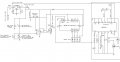
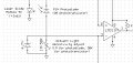
Haven't posted for a while, but I need some help with what could be a problem with photodiode use and a possible solution. I am using a photodiode in reverse-bias mode as a laser light detector (see attached schematic). The photodiode when supplied with +5V will put out 5.5V or more when the laser ( or other light source ) is brought right up close to the photodiode. As I understand this is normal behaviour for a photodiode. The overall circuit works great, but I have a concern that any voltage above 5V is going to cause damage to the LM311 comparator which has a 5V supply and 0V ground. As a possible solution I incorporated a 4.7V Zener diode around the sensitivy adjust pot ( no laughing in the back row, I'm only a novice! ). This seems to work after a fashion, but I didn't realise that these diodes draw a small amount of current. The result is that its use greatly decreases the sensitivity and upper voltage level that the photodiode can produce due to the fact that the Zener is drawing on what little current the photodiode can pass. I tried removing the Zener and swapping round the photodiode and 1M pot so that the photodiode can 'pull-down' the 5V supply but I found that this would result in a negative input to the comparator of less than -0.5V confused. Again, I am wondering if this can damage the LM311 which has it's ground at 0V. If these kinds of inputs are going to be a problem, any ideas how I can get round this?
Thanks,
Salvatore.
Haven't posted for a while, but I need some help with what could be a problem with photodiode use and a possible solution. I am using a photodiode in reverse-bias mode as a laser light detector (see attached schematic). The photodiode when supplied with +5V will put out 5.5V or more when the laser ( or other light source ) is brought right up close to the photodiode. As I understand this is normal behaviour for a photodiode. The overall circuit works great, but I have a concern that any voltage above 5V is going to cause damage to the LM311 comparator which has a 5V supply and 0V ground. As a possible solution I incorporated a 4.7V Zener diode around the sensitivy adjust pot ( no laughing in the back row, I'm only a novice!
). This seems to work after a fashion, but I didn't realise that these diodes draw a small amount of current. The result is that its use greatly decreases the sensitivity and upper voltage level that the photodiode can produce due to the fact that the Zener is drawing on what little current the photodiode can pass. I tried removing the Zener and swapping round the photodiode and 1M pot so that the photodiode can 'pull-down' the 5V supply but I found that this would result in a negative input to the comparator of less than -0.5V confused. Again, I am wondering if this can damage the LM311 which has it's ground at 0V. If these kinds of inputs are going to be a problem, any ideas how I can get round this?Thanks,
Salvatore.
Attachments
-
 36.1 KB Views: 159