Pedalboard power supply - help

Thread Starter

dimi3

Joined Oct 25, 2008
7
Hi,

I’m new to the forum, and looking for some info and help for my project. I’m a guitarist myself and facing the problem as many others do, powering bunch of hungry pedals from one power supply on the pedal board.

What I would like to do is regulated power supply with isolated outputs to avoid ground loops, using a torodial transformer with multiple secondaries, and I want that its totally hum free and clean.

Why I want to build it? It’s only a power supply. Because what is currently on the market costs 200$ + with decent quality, and most of them are underrated with mA of current for my needs.

Then I need to pack it to very compact enclosure e.g. (6" x 3.4"x 1.75")

Specification for the supply would be something like:

Build as many outputs as you need.
9V,12V or 18V since each rail is separated this could be easily achieved.
Up to 1,5A per rail, depends on transformer selection. (Typically ordinary pedals need less then 100ma, but some also 300 and 400mA).

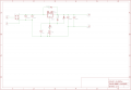
I searched the net for similar projects and found bunch of ideas, how to approach this. The best project I found was http://www.audioxpress.com/magsdirx/...tipton2926.pdf, but its huge rack version with ordinary transformers, and its missing some kind of DC protection circuit.

The PCB layouts are also available for this, but I thing that it could be done more compact, since I won’t putting it in the rack enclosure, I’m not really a PCB designer so I would need some help around this. If someone has some spare time to help I’m willing also to pay for the design. Basically what needs to be done is only 1 rail of power supply which is then copied as many times as many outputs somebody needs.

So my questions for all the good and experienced people on this board:

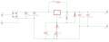
What is your opinion on the schematic regarding of hum issues DC filtering?
Do you think there is a need of adding DC protection circuit to each output?

If anyone is interested in building something like this (some guitar players on board) join the thread.

I will really appreciate all the comments on this topic.
 

mik3

Joined Feb 4, 2008
4,843
If you are not familiar with electronics i suggest you to buy one because it will be much better than a built one. Things are not as simple as you think.
 

Thread Starter

dimi3

Joined Oct 25, 2008
7
thanks for warning:) I have the experience of building project, but I never did my own design, so that was the reason asking for help here.

I drew schematic in Eagle, this is the best I can do, if someone could check for errors I would be more than grateful.
 

Attachments

John Luciani

Joined Apr 3, 2007
475
You should post your schematic as a pdf file for people that do not have eagle.

I would add current limit to each output.

I am not sure of your experience level. If you have not done many projects I would
stick with the linear supply. Personally I would do a switching supply with a switching
frequency above the audio range.

(* jcl *)
 

Thread Starter

dimi3

Joined Oct 25, 2008
7
thanks for the input, Im attaching also the schematic picture of current circuit.

Regarding the experience I would say advanced beginner :).

@John do you maybe have example of switching power supply that you are mentioning? I tought that switching power supplyes produces more hum and noise??

thanks again for the input.
 

Attachments

SgtWookie

Joined Jul 17, 2007
22,230
Your rectifier bridge as shown has a 1A rating. It should have a higher rating than the LM317, which is 1.5A. A standard rectifier bridge will drop about 2v across itself; 1V for the + side and 1V for the - side. Using a low-rated bridge will cause the voltage drop to be significantly higher.

R1 really isn't necessary.

You have R2 at 240 Ohms. That is for an LM317L circuit. For an LM317, you should use 120 Ohms for R2. That is because an LM317 requires a minimum of 10mA current to provide guaranteed regulation.

Vref (the voltage between the OUT and Adj terminals) is typically 1.25V, but it may range from 1.2V to 1.3V. If R2 is 120 Ohms, then a minimum of 10mA current is guaranteed. 1.2V/120 Ohms = 10mA.

Use 330 Ohms for R3. This will give you a minimum output of around 5V.
Use a 1K pot for R4. This in conjunction with R3 will give you a range of 5V to Vin-1.7.

R5 is unnecessary. R2+R3+R4 will draw the required 10mA minimum load. When the input AC is removed, R2+R3+R4 will eventually discharge the caps on both sides of the regulator.
 

John Luciani

Joined Apr 3, 2007
475
@John do you maybe have example of switching power supply that you are mentioning? I tought that switching power supplyes produces more hum and noise??

thanks again for the input.
I don't have an example of a switching converter that is isolated (which I agree would
be desirable in your application). I have been doing mostly battery powered converters.
I have been using the On-Semi NCP1421 and Linear Technology LT193x parts.
Unfortunately these parts do not provide an isolated output.

There are a lot of makers of switching converter ICs ---On-Semi, Texas Instruments,
Linear Technology, Maxim and National Semiconductor. I would try TI first for
your application.

You could prototype a switching converter to see if the noise is a problem. Choose a
frequency that is well above the audible range and do a good layout and you should not
have a problem. I would do a wall transformer to step down the AC voltage to
a DC voltage that is a few volts above your requirements. I would then do isolated
converters for each output.

The problem you may have with a switcher is that the controller ICs are usually available only in SMD packages.

Pictures of some of my power supply boards are at http://tinyurl.com/6jm8tu
Some more power supply board pictures are at http://tinyurl.com/5rfmrz

(* jcl *)
 

Thread Starter

dimi3

Joined Oct 25, 2008
7
thanks for all the inputs @John, thanks for the suggestion, but I dont feel that I can design more complex circuit, I would like something easy rather to work at the end:) If I will start something complex it may happen that I will get totaly lost.

@SgtWookie, I made all the corrections you suggested( please see updated pic).

I will made 5 isolated outputs 4 with 12V@400mA each.
1 9V output 400mA.

Do you think that for less then 0,5A I need to change the bridge rectifier? The current draw of guitar pedals I use is 300mA each.

Will I be able to fine tune the ouptut voltage with suggested R3 +R4 from 9V to 12V?

Thanks again for your help.

Bottom line I need as clean and hum free power supply, becouse the signal from pedal is amplifided in guitar amp, and if something is causing hum on the pedal it's also amplified.
 

SgtWookie

Joined Jul 17, 2007
22,230
I made all the corrections you suggested( please see updated pic).
OK, looks good so far.

I will made 5 isolated outputs 4 with 12V @ 400mA each.
one 9V output 400mA.
That's do-able.

Keep in mind that you WILL need to use heat sinks for the LM317's. The TO-220 versions have Vout on the tab, so you must either use insulated heat sink mount hardware like this:
http://www.radioshack.com/product/i...kw=heatsink&origkw=heatsink&parentPage=search
or make sure that your heatsink can't contact anything conductive (like the case). Use heat sink grease to improve thermal conduction.

With 18V in and 9V out @ 400mA load, an LM317 will be dissipating about 3.7W. Same load, same input voltage, 12V out will be dissipating about 2.5W.

Do you think that for less then 0,5A I need to change the bridge rectifier? The current draw of guitar pedals I use is 300mA each.
Well, if you're going to have a known lower current draw, then fuse the supply. Faster, easier and cheaper to replace a fuse than a rectifier bridge. Use a 1/2A, slow blow fuse.

Will I be able to fine tune the ouptut voltage with suggested R3 +R4 from 9V to 12V?
Yes; over a broader range than that.

If you want to narrow the range of adjustment, you could use a 620 Ohm fixed resistor for R3 and a 500 Ohm resistor for R4. Your output range would then be from about 8V to 13V.

Bottom line I need as clean and hum free power supply, becouse the signal from pedal is amplifided in guitar amp, and if something is causing hum on the pedal it's also amplified.
Understood. It should be pretty quiet. The large caps on the input and output will help quite a bit.
 

John Luciani

Joined Apr 3, 2007
475
thanks for all the inputs @John, thanks for the suggestion, but I dont feel that I can design more complex circuit, I would like something easy rather to work at the end:) If I will start something complex it may happen that I will get totaly lost.
That sounds like a sensible approach.

When you are ready to try a switcher take a look at the application notes. There
is usually a recommended component list and PCB layout. If you do not deviate
too much from the recommended designs you should get good results.

The biggest obstacle (for an advanced beginner) will be the SMD components.
With the proper tools I find that SMD assembly is much quicker.
My tool recommendations are at http://tinyurl.com/5foeou

(* jcl *)
 

Thread Starter

dimi3

Joined Oct 25, 2008
7
thanks for all the help, I corrected schematic, and add a heatsinnk to LM317.

Regarding the input voltage is 18V enough? Or I should go for higher voltage? I didnt order transformer yet so I could still change my mind:).

In oroginal design the 2 recifiers wore 1N4003, since I didnt find the part in Eagle library I put in 1N4004 is this ok?

I'm a little lost in Eagle now, I dont know how to copy schematic 5 times, to get 5 independent rails of power supply??

I'm attaching the latest schematic in sch and picture format.
 

Attachments

SgtWookie

Joined Jul 17, 2007
22,230
Regarding the input voltage is 18V enough? Or I should go for higher voltage? I didnt order transformer yet so I could still change my mind:).
You're going to lose about 2V across the bridge rectifier (1V for each side) and 1.7V minimum across the LM317, for a total loss of about 3.7v. Specs on your actual bridge rectifier may vary. Look at datasheets for your candidate bridges to see for certain. 1N4001 through 1N4007 diodes will have a Vf (forward voltage) of roughly 0.85V at 400mA current at 25°C, and 1.1V @ 1A continuous.

In original design the 2 recifiers wore 1N4003, since I didnt find the part in Eagle library I put in 1N4004 is this ok?
Yes. Basically, all of the 1N4001 through 1N4007 series diodes have the same characteristics except for the PIV (peak inverse voltage, or reverse voltage.)
1N4001=50V
1N4002=100v
1N4003=200v
1N4004=400v
1N4005=600v
1N4006=800v
1N4007=1000v

You CAN use the "Name" command to change it from 1N4004 to anything you'd like. Read on.
I'm a little lost in Eagle now, I dont know how to copy schematic 5 times, to get 5 independent rails of power supply??
Here's a link to a good tutorial:
http://www.sparkfun.com/commerce/tutorial_info.php?tutorials_id=57&sipp=1&page=8

I suggest you read through it and try some things before you get too deeply into it. It will spare you a good deal of grief.

But basically, to copy and paste sections of a schematic:
1) Use the "Group" tool (dashed box) to define the items to be copied. Draw a box around them, or click points to define the boundaries.
2) Click on the "Cut" tool (scissors).
3) Right-click on the point of the selected area that you want to use as the reference point. The selected items are then copied to the buffer.
4) Click the "Paste" tool (to the right of the "Cut" tool; a brush spreading yellow paste). The items previously copied to the buffer will then follow the cursor around. Left-click to drop it where you want it.

A couple of controls you need to get familiar with are the "Name" and "Value" buttons. "Name" looks like a resistor symbol with R1 highlighted. "Value" looks like a resistor symbol with 10k highlighted. Each "Name" must be unique. These are reference designators, and also signal names. If the signal names are the same, Eagle will want you to connect them all together in the PCB layout portion. This can cause big problems!

"Value" should have something meaningful in it - for a component or a pad.

On the left, you have two pads; one named "PAD1" and one named "AC". I suggest you rename these to L3 and L3RTN.
The primary side of your toroidal transformer will have connections for L1 and N (Neutral) or L1 and L2 if wound for 240VAC. The secondary windings will be L3, L4, etc.

On the right, you have PAD3 and PAD4; both have a "Value" of 12V. You could instead call them +VOUT and -VOUT or VOUT and VRTN. This would be generic enough so that you could use the same PCB layout for both voltage designs, and you would also know which pad was more positive, and which more negative.

I suggest that you don't need to repeat the same circuit five times; just make a number of circuit boards and wire them together during final assembly. This will make replacements in the field much easier. You could make a couple of spare boards, and set one for 9V, another for 12V. If one in use blows during a performance, just replace the board.
 
Last edited:

Thread Starter

dimi3

Joined Oct 25, 2008
7
Thanks for all the inputs, I'm playing with the PCB :) it’s not that difficult, but it takes a lot of time for the first project.

I'm still not quite sure about transformer secondary voltage.

e.g. I take 15V secondary’s, bridge rectifier drops the voltage for 2V and another 2V for LM317, so I’m on 11V. I read that smoothing increases the voltage for 1,4X DC rectified, so it should be then around 15V?

I don’t want to go too high to have the overheating problems with LM317.

What do you think?

Thanks.
 
Top