Output capacitor coupled class b push pull. Need explanation.

Thread Starter

nik2009

Joined Jan 17, 2010
13
Hello,

Class B push pull amplifiers like the one shown here http://www.allaboutcircuits.com/vol_6/chpt_6/10.html

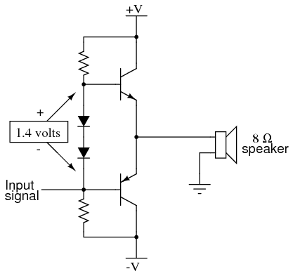
are explained when it comes to class b push pull amplifiers in the sources I have found.

But I have encountered class b push pull like the one shown in the attachment. Afaik it works in the following way. There is 10V with respect to the ground on the output coupling capacitor. As a result each transistor gets 10V between the emitter and the collector and the polarities are correct. When the positive swing of the input comes NPN conducts and the capacitor charges. When the negative swing comes PNP conducts and the capacitor discharges. (So, when the negative swing comes the capacitor becomes the "power supply" of the circuit)

My doubt is: What if the input signal comes like the attached example. The positive swing is much "larger" than the negative one. If the capacitor is charged during the positive swing, say, from 10V to 13V (10V + 3V) with respect to the ground, than it is discharged during the negative swing to 12V (13V - 1V) with respect to the ground, than during the next positive swing it charges to 15V (12V + 3V), and so on. I know the amplifier does not behave the way I just described (I have done a simulation). I know it is a very stupid question but I can't figure out why it behaves the way it does and not the way I described for the life of me :)

Thanks a lot!
 

Attachments

Thread Starter

nik2009

Joined Jan 17, 2010
13
Thanks Audioguru.

Does the shown input signal bring additional DC offset voltage (besides 10V)?
 
Last edited:

Thread Starter

nik2009

Joined Jan 17, 2010
13
Could you please answer one more question.

If we get rid of DC and now there is 0 where the average is shown on your graph. The positive and negative swings are still asymmetric but the capacitor passes that kind of signal just as well as it would pass an ideal sine wave.

I mean, when passing a sine wave (or any signal having symmetrical swings and RC >> T) the capacitor gets charged to some value Q_charge during the positive swing than it discharges Q_discharge during the negative swing. The positive and negative swings of a sine wave are symmetrical so, Q_charge - Q_discharge = 0.

But the signal I have shown has asymmetrical swings (even when we get rid of DC) and the capacitor passes it as well (so, Q_charge1 - Q_discharge1 = 0) as a sine wave. Why?

Thank you!
 

thyristor

Joined Dec 27, 2009
94
Because the asymmetry is "caused" by there being a DC level on the signal. Remove the DC level (with the capacitor) and the signal is symmetrical. ie: every signal can be considered to be a symmetrical signal plus a DC level. With a capacitor in series the DC level becomes zero and we are just left with the symmetrical signal.
 

Thread Starter

nik2009

Joined Jan 17, 2010
13
Thanks thyristor.

But:


If the red line is the zero level then the positive and negative swings amplitudes are equal. But their shapes are still different. So the swings are still asymmetric.
 

hobbyist

Joined Aug 10, 2008
892
Look at your signal, there is no accumalation of charge on the capacitor output side, as would be expected, because once the capacitor output signal drops below zero, and goes one volt neg. the capacitor is fully discharged and now recieves a fresh neg, signal, then when it reaches zero going positive the capacitor is again fully discharged, to recieve a fresh positive 3volt wave, so there is no accumalation of charge, but rather a complete discharge at every half cycle.

Only if the capacitopr output never reaches zero to change in amplitude direction, woyuld you have an increase in voltage of the greater amplitude, this caze positive going signal.

That's my theory of why there is a output that matches the input wave form.
 

hobbyist

Joined Aug 10, 2008
892
Audioguru
I agree based upon your expertise in this field, versus my basic understanding of electronics, however let me explain my view on this, and point me in the direction where I'm making the mistake in this analysis. Thankyou.

The net voltage on the output side of a coupling capacitor, will be at zero volts, respect to ground. (or is that assumption my mistake already?)

So when a positive signal comes in it raises the net voltage to that value above ground. (net, meaning the voltage value difference above the standing offset voltage)

Then when the signal drops in amplitude the voltage is still present, until the input signal to the capacitor, is driven opposite polarity, which I thought would have to fully discharge the capacitor, so as to accumulate a negative potential with respect to ground.

And if the voltage input never drives opposite polarity, than the voltage on the output side of the capacitor would integrate, accumulate a charge with every input.

So please show me how I got way out here in left field.

Like I said I agree with what you said, just don't know how to reconcile my understanding of what you said to my very vague knowledge of coupling capacitances.

Thankyou.
 

Audioguru

Joined Dec 20, 2007
11,248
When the power supply to the amplifier is turned on, the output capacitor immediately fully charges to half the supply voltage. The output of the capacitor is at 0V.

The input to the capacitor has an AC signal that frequently rises and drops in its DC voltage.

If the input to the capacitor rises 3V then the output of the capacitor rises to +2.99999V. When the input of the capacitor passes its idle voltage then the capacitor completely recharges to half the supply voltage.

If the input of the capacitor drops 3V then the output of the capacitor drops to -2.99999V. When the input of the capacitor passes its idle voltage then the capacitor completely recharges to half the supply voltage.
 

hobbyist

Joined Aug 10, 2008
892
This is one of those hand against head, "wow I could of had a v8 moments",
I apologize, thanks for taking the time to explain something that was so obvious to us who is trained in amp design, with having the quiescent bias voltage at the output,

I got so caught up in what the OP was saying about negative signals and such, I got completely drawn off of the very basics of quiescence where the output is just a fluctouation of the quiescent voltage DC value to start off with.

My question in light of the very basics of amp design was stupid for me to ask, sorry for being a pain,. (boy I feel embarrassed)

Thanks again for being patient with me and getting me back to basics.

Have a great day...
 
Top