I am having a problem with controlling a LED through an Optoisolator (NEC2532) from an arduino microcontroller.
Problem: I expected the LED to be off until I trigger the Optoisolator similar to the following but trigger a LED instead of a Flash unit.
http://www.glacialwanderer.com/hobbyrobotics/?p=10
Opto Spec Sheet: http://www.sparkfun.com/datasheets/Components/PS2532-Optoisolator.pdf
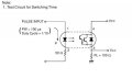
Investigation: I have hooked a NEC2532 Optoisolator across the output on Arduino Output Pin 4 to Opto Pin 1 then from Opto Pin 2 to 50 Ohms resistance then to Ground on the Arduino Board. The opto is trying to control the on/off state of and LED. The LED is connected as follows: Arduino Pin 8 to 1k ohm resistor then to Pin 3 on the Opto then from Pin 4 on the Opto to a LED then from the LED back to ground on the board.
Results:
I have Pin 4 (Control to the opto) set to LOW and Pin 8 (power for the LED) set to be ON 1/2 second then Off 1/2 Second. I expected the LED to remain off until I triggered Pin 4 to a logic HIGH state but the LED blinks like the Opto is not direct shorted from Pins 3 and 4 on the opto.
Anyone got an Arduino that can tell me what I am doing wrong? Or does anyone know why the Optoisolator is letting pins 3 and 4 act shorted?
Problem: I expected the LED to be off until I trigger the Optoisolator similar to the following but trigger a LED instead of a Flash unit.
http://www.glacialwanderer.com/hobbyrobotics/?p=10
Opto Spec Sheet: http://www.sparkfun.com/datasheets/Components/PS2532-Optoisolator.pdf
Investigation: I have hooked a NEC2532 Optoisolator across the output on Arduino Output Pin 4 to Opto Pin 1 then from Opto Pin 2 to 50 Ohms resistance then to Ground on the Arduino Board. The opto is trying to control the on/off state of and LED. The LED is connected as follows: Arduino Pin 8 to 1k ohm resistor then to Pin 3 on the Opto then from Pin 4 on the Opto to a LED then from the LED back to ground on the board.
Results:
I have Pin 4 (Control to the opto) set to LOW and Pin 8 (power for the LED) set to be ON 1/2 second then Off 1/2 Second. I expected the LED to remain off until I triggered Pin 4 to a logic HIGH state but the LED blinks like the Opto is not direct shorted from Pins 3 and 4 on the opto.
Anyone got an Arduino that can tell me what I am doing wrong? Or does anyone know why the Optoisolator is letting pins 3 and 4 act shorted?