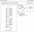
I am putting together a pcb for an octal inverter (MM74HC240) to replace a hex inverter circuit in a system. The hex inverter IC simply has 6-inputs, 6-outputs, a 5V and a ground. The octal inverter has the 8 normal inputs and outputs and the supply but there are two other pins that connect to the inputs/outputs. What do these do?
Thanks in advance,
MM
Thanks in advance,
MM