Non-Zero Output for Phase Shift Circuit in Off Mode

Thread Starter

moot

Joined Sep 20, 2009
46
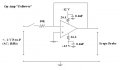
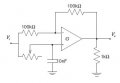
I've just put together a circuit that takes an AC input, and shifts its phase between 0-90 degrees. I've included a slightly simplified circuit diagram as an attachment (the only difference is that I've strung two of these in series to increase the phase shift range).

I'm using a TL074ACN IC, powered by +/- 12 V, with 0.1uF capacitors to ground.

My input is +/- 2 V AC at 1kHz.

Here's my problem:

When I turn on the input voltage, the output looks fine. The phase shift works beautifully.

When I turn off the input voltage, the signal flatlines to zero, but then slowly rises to a DC 10 V signal and stays there. It's such a simple circuit, and I've checked and rechecked (and rechecked!) my wiring, that I'm clueless as to what could be wrong.

Any ideas?
 

Attachments

Thread Starter

moot

Joined Sep 20, 2009
46
Try a load resistor on the input to give the op amp a reference to ground.
Done. I've tried a 1k, 10k, 50k, and 1M, and the problem remains.

(I should've done that anyway, though, so I'm sticking with the 10k between the input and first op amp.)

If I touch the input wire going to the first op amp with my finger, the signal goes to zero. Does that mean my op amps may not be grounded properly?

EDIT: Nevermind, I spoke to soon. When I hold the input wire, the signal DOES NOT go to zero, it still goes to ~12 V.
 

Thread Starter

moot

Joined Sep 20, 2009
46
UPDATE

I've decided to isolate the IC, and just test it with a follower. I've attached a new diagram with my current wiring. The problem persists! When the switch is closed, the scope shows me the input voltage, as I would expect. When the switch is thrown open, the voltage flatlines and then rises to ~10-12 V and stays there.

I'm pretty much new to working with op-amps, IC's, and the like - but I've read through a fair number of electronics books, so I thought I had a basic understanding of them (..'til now).

It has to be a power issue (of the op-amps), right? I've got the low-pass filter to the power thrown in to filter out high-frequencies. What else could I check? Thanks!
 

Attachments

Audioguru

Joined Dec 20, 2007
11,248
Your second schematic shows an opamp with its output at 0V no matter what is the voltage at the input. It is not a follower.

If it really is a follower and you are disconnecting its input (the + input of the opamp) then its input is floating without a reference voltage and then the opamp will do anything.

The first circuit must also have its input at 0VDC. It can have AC so can be driven from the output of an opamp that is biased at 0V.
 

Thread Starter

moot

Joined Sep 20, 2009
46
Your second schematic shows an opamp with its output at 0V no matter what is the voltage at the input. It is not a follower.

If it really is a follower and you are disconnecting its input (the + input of the opamp) then its input is floating without a reference voltage and then the opamp will do anything.

The first circuit must also have its input at 0VDC. It can have AC so can be driven from the output of an opamp that is biased at 0V.
Hmm, I see. I've inserted a current-to-voltage converter at the beginning of the circuit, and removed the follower. The circuit now operates correctly.

Thanks for your input.
 
Top