Need to build a battery drainer

Thread Starter

mglenney

Joined Jan 16, 2008
1
Sounds silly, doesn't it? I am an electronics guy from days past and I am helping my son with his science fair project. His project is to test different battery brands and see how long they last. I want to use this opportunity to introduce him to electronics and circuit building instead of just using flashlights or something else already built.

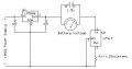
My plan is to build a simple circuit with a light bulb (or multiple), battery and switch. I figure with multiple light bulbs wired in parallel we will pull more current and drain the batteries faster. My questions are:

  1. How do I make sure I'm not pulling too much current from a battery? I don't want them to get to hot or maybe cause damage to the battery and/or possible harm to my son. We haven't decided on what size battery to use. At this point it doesn't matter. Where can I find out how much current each size battery can handle?
  2. Does anyone have any neat ideas on how to tell how long the battery lasted? Maybe an inexpensive analog timer we could use inline that would just stop counting up when the battery is drained? He is planning on using a watch or stopwatch to track it but I thought something like that would be neat.
  3. What am I not thinking about? I was an AT in the Navy so I had extensive training in electronics. Unfortunately, when you get to your squadron you swap parts instead of building circuits so my knowledge is mostly book based and I don't want to miss a step.

Thanks,

Mike G.
 

scubasteve_911

Joined Dec 27, 2007
1,203
Hi Mike,

The problem with measuring battery capacity is maintaining a constant load under varying voltage. A resistor, for example, would cause a current draw that is proportional to voltage. So, if a particular battery had a different "Capacity left vs. Voltage curve, then you might be unfairly gauging battery capacity.

Typically, 'they' monitor both current draw and voltage level at the same time until the battery hits its cutoff voltage. This gives a fair representation of battery capacity.

Due to this being for a science fair and not a consumer report, you can probably simplify things up a bit. I would use a simple resistor across the battery, maybe choose to draw about 1/10 * C of the battery. So, if it is ~1000mAH, then about 100mA. Be sure to pick an appropriate wattage (I^2 * R) * 2(min)and try to get low temperature coefficient if you can.

Then, you should set up a simple 5V supply and power a voltage comparator. This will be set to the cutoff voltage of the battery. You can wire the output to the gate of a logic level mosfet, which you can tie between the switch of a small electronic stopwatch. Then, it can have an automatic shutoff after you engage the measurement. You may need to try a couple different stopwatches, since the control circuitry may switch on the rising or falling edge of a signal. I'm not sure how long these things can run for, I'm going to look into it..

after a quick check, found a 24hour one :)

http://cgi.ebay.com/Digital-Sports-...ryZ44076QQssPageNameZWDVWQQrdZ1QQcmdZViewItem

If you need clarification, then please inquire. Good luck!

Steve
 

Audioguru

Joined Dec 20, 2007
11,248
Some batteries have a "best before" date. Note the date in your report about how long they last because an old battery has self-discharged quite a lot.

Look at all the Chinese batteries that are leaking in their packages at The Dollar Store. They have been on a boat and in the store for many years.
 

beenthere

Joined Apr 20, 2004
15,819
If you want to add an inexpensive visual indicator, look at the data sheet for an LM3914. It can be set up to have all the LED bars glowing with a fresh battery, and they will go out one by one as the voltage diminishes. It would need an other battery to keep it running.
 

nomurphy

Joined Aug 8, 2005
567
Look at the datasheet(s) for three-terminal regulators (LM317), the apps section will usually show a constant-current sink design.
 

Audioguru

Joined Dec 20, 2007
11,248
An LM317 constant-current source is not suitable to discharge a 1.5V battery cell. Its minimum input voltage is 3.75V.
A power resistor is fine if you obseve whow long it takes for the battery cell's 1.5V voltage to drop to 1.0V.
 

KMoffett

Joined Dec 19, 2007
2,918
We use something like this to characterize solar panel V-I curves. In our case the regulator is a $250 voltage-controlled constant-resistance module. In order to take the PV panels down to 0V the module needs a series voltage source to compensate for the regulator overhead. The attached circuit does the same thing for the LM317 as a constant-current load for a 1.5 volt battery. A quick bench test looks like this will do what the OP would need to duplicate discharge conditions. See any glaring problems?

Ken
 

Attachments

Top