need opinion and guidance about transistor amplification...

Thread Starter

aj_snowfire

Joined May 19, 2010
16
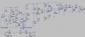
guys do u think this schematic can atleast transmit a range of 3meters, or do u think more,if more how much could it be....
and do u think the schematic is meaningful...
1)do u think its better to have a buffer amp(current amp) after the oscillator stage instead of voltage amplifier...........
2)and please tell me some tips to improve the range..
thank u in advance..
" http://images.elektroda.net/84_1274205254.jpg "
here's the schematic
 

Audioguru

Joined Dec 20, 2007
11,248
The very old FM transmitter circuit has a lot of output power. It is illegal in most countries. If the transmitting and receiving antennas are 80cm long and are parallel, its range should be about 5km to a very sensitive hi-fi tuner or car radio. Its range should be across the street to a cheap "radio" from The Dollar Store.
 

Audioguru

Joined Dec 20, 2007
11,248
how do u say it s a very old transmitter circuit.......please clear my doubt
Yes the very old FM transmitter circuit uses the very old 2N2219 video transistors that use a Mickey Mouse clip-on round heatsink.
I don't think its vari-cap diodes are made anymore.
 

Thread Starter

aj_snowfire

Joined May 19, 2010
16
u were talking about the transistors,do u think the 2219 can be replaced by some new modern transistors like SD1274
 
Last edited:

Thread Starter

aj_snowfire

Joined May 19, 2010
16
but i have bought MV2109 about 5weeks ago,i think its still in stock,
and do u think its better to use a buffer amp next to the oscillator stage,so that the oscillator output would have high impedance,..........
 
Last edited:

Audioguru

Joined Dec 20, 2007
11,248
I have never made a fairly high power illegal FM transmitter.
In most countries you need to get a licence to be a radio station, the authorities will give you a certain frequency and allow you to have a certain type of program. The transmitter must be certified to have a fixed frequency (the circuit you found wanders its frequency all over the place) and low harmonics.

The circuit you found is missing the pre-emphasis equalization FM radio stations have (it will sound muffled) and is mono, not stereo.
 

Thread Starter

aj_snowfire

Joined May 19, 2010
16
i'm not goin to build it,and i dont have any intentions to build a radio station.....
i just asked will the transmitter,and some weeeks back i have a made a fairly stable oscillator,which had a range of 3meters with out RF amplifier and antenna...
do u think this 3 stage amplification works well or not,just give me some tips and u r opinions,i wanna learn.....please
 

Attachments

Audioguru

Joined Dec 20, 2007
11,248
A dummy load is not an antenna so your transmitter is simply heating the resistor instead of transmitting.

Maybe you must learn about how antennas work.
 

retched

Joined Dec 5, 2009
5,207
A dummy load is not an antenna so your transmitter is simply heating the resistor instead of transmitting.

Maybe you must learn about how antennas work.
Thats absolutely right. Just because you see antenna with a 50ohm impedance, does not mean a 50omh resistor does the trick.

Dummy loads used in radios are to help "tune" the system to see a closer to perfect 50ohm antenna.
 

Thread Starter

aj_snowfire

Joined May 19, 2010
16
yes, i know that,i can't include a antenna in a simulator......u know that,and i know wat is antenna....no doubt about it...
as RF systems use 50ohm load,so the 50Ohm resistor represents the antenna in the simulating software....
,the output of the circuit can be connected to a antenna with a co-axial cable and kept 30meters high....
 

Thread Starter

aj_snowfire

Joined May 19, 2010
16
antennas convert electromagnetic radiation into electrical current in receivers and converts electrical current to electro-magnetic radiation in transmitters......
i think this is correct
 

Thread Starter

aj_snowfire

Joined May 19, 2010
16
the collector voltage goes more than the supply to the collector when there is a inductor load(inductor coil made by #18 guage CU wire) at the collector,if the value of the inductor is increased then the Vc will also increase...cause when the transistor goes to OFF Phase,then the energy stored in the collector inductor is released,which increases the voltage at the collector..
protection diode can protect a transistor which has a Inductor or a relay at its collector... if a diode is places across the inductor,i think like this one in the image(diode D3) " http://images.elektroda.net/15_1274548562.jpg "
but the diode limits the voltage swing at the collector.
It(diode) will conduct electricity when the voltage across its terminals reaches a certain value.
and can u please tell me how can i know that from the datasheet(of a diode),the voltage value till it can conduct and if the voltage increases it will become open circuit to protect the transistor from high voltage damage...
help me out...
 
Top