Hello, I'm a newbie in electronics and i'm trying to understand all the info as fast as possible; however, i need to build a simple series LED circuit but i'm not sure if i am on the right track.
First, get all of the 20mA LEDs together in series.
Then, you have a special case - one LED is rated for 10mA @ 2.6v. You will need to parallel that LED with a resistor to achieve a total current of 20mA.
So, what size resistor will you need to make up the 10mA across 2.6v?
R=E/I, or Resistance(Ohms) = Voltage / Current(Amperes)
R=2.6v/10mA = 2.6/0.01 = 260 Ohms.
Now you can put that 260 Ohm resistor in parallel with your "odd duck" 10mA @ 2.6v LED, and you'll be able to put it in series with the other 20mA LEDs.
You'll still need another resistor to limit current through all of the series LEDs.
Rlimit = (Vsupply - VfLED(total)) / DesiredCurrent
where VfLED(total) is the total of all of the LED forward voltages.
So, you still have apples and oranges. One LED needs 28mA, the others need 20mA.
Now what you'll need to do is to add up the Vf of all of your 20mA LEDs.
Then you will need to figure out what resistance you can parallel that series "string" with to provide the extra 8mA current required for your "odd duck" 28mA red LED.
Once you have all of the LEDs in series with common 28mA current, it's duck soup, right?
[eta]
It'll help a lot if you re-draw your schematic with all of the 20mA LEDs shown together in series, with a resistor in parallel to the entire string of them, then the odd duck 28mA LED by itself, and then another resistor in series with the entire string.
you've mis-calculated the value for R1. It should be 245 Ohms.
R1=(12v - (3.7+1.7+1.7))/20mA = (12-7.1)/0.02 = 4.9/0.02 = 245 Ohms
R2 is also incorrect.
R2=(12v - 2.6v)/28mA = 9.4/0.028 = 336 Ohms (rounded off)
You can go up to the next higher standard value of resistance, or use resistors in series and/or parallel to get the resistance value you need.
A table of standard resistor values is on this page: http://www.logwell.com/tech/components/resistor_values.html
Hobbyists typically use E12 or E24 values.
Are you planning on using this circuit powered by a computer supply, or possibly in an automobile? If the latter, you should be aware that the supply voltage will vary quite a bit.
Thank you so much for your help. I learn something new every day. This is actually my second day researching all about circuits, and i'm digging this stuff jeje...of course...there is so much to remember.
This is going to be used as interior accent lighting in a car. A little touch of tech. I used a multimeter to measure the source, and it's a steady ~12v.
I'm gonna build this set up now as per your specs. I'll send you pictures.
A car battery is about 12.6V when it is fully charged and has been sitting all night not doing amything. Then the alternator boosts the voltage to up to 14.4V when the engine is running.
Red LEDs are not more than 2.2V so your 2.6V odd-ball is wrong.
My ordinary 5mm red LEDs are typically 1.76V at 20mA and 1.85V at 30mA.
My Luxeon Super-flux red LEDs are typically 1.95V at 20mA, 2.0V at 28mA, 2.1V at 40mA and 2.2V at 70mA.
Yes, if you're going to use them in a vehicle, you will need to either regulate the voltage across your two parallel strings, or individual current regulation for each string.
When you are starting the engine, the voltage can drop well past 10v, and right after it starts, the voltage may go as high as 15v. Simple resistors are not enough to provide proper current limitation when the supply voltage can vary so much.
The current regulation method is quite easy if you use an LM317 adjustable voltage regulator IC. You connect a 62 Ohm resistor from the OUT terminal to the ADJ terminal, and your LED string between the ADJ terminal and ground. Then you connect the supply voltage to the IN terminal. This will give a 20mA current through the LED string.
The LM317 will drop at least 3v across itself when used in this way. So, if you started off with 12v, you have to subtract 3v from that, which leaves 9v. You could power several LEDs in series, as long as the total Vf of the LEDs is less than or equal to 9.
The key to the whole thing is the 62 Ohm resistor. This will cause the regulator to put out 20mA (nominally).
If you want more or less current, you can calculate:
Resistor = 1.25/Desired Current (desired current must be between 10mA and 1.5A, inclusive.)
So, if you wanted 30mA output:
R = 1.25/30mA = 1.25/0.03 = 41.6 Ohms
The closest standard value is 43 Ohms
We can work the formula backwards, too:
Current(Amperes) = 1.25/Resistance(Ohms)
I = 1.25/43 = 29mA (rounded down)
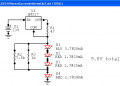
R1 causes the LM317 to output roughly 28mA in current regulator mode.
R2 in parallel with R3 results in 882 Ohms.
The three 20mA LEDs have a total Vf of 7.1v
7.1v/882 Ohms = 8mA (rounded off)
All of the LEDs in series have a total Vf of 9.8v
The LM317 when used as a current regulator has a Vf of roughly 3v
So, the total voltage required to run the circuit is 9.8+3 = 12.8v
As long as your alternator is creating an output, or even if your engine is off but your battery is fully charged, your LEDs will maintain normal (full) brightness.
If you want the LED brightness to be unchanged at lower voltages, you'll either need two LM317 regulators in current regulation mode, or a single LM317 in voltage regulator mode with current limiting resistors on the LEDs.


")