Need help with schematic

Thread Starter

laserboy1

Joined Aug 1, 2009
6
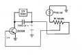
Hello there, i'm quite new to electronics but i already did some cool projects, now i am bussy making a laser triggerd alarm, and here is the schematic for the alarm, the laser will light up the photocell and when you go through the beam, the alarm should work. But first i need some help with this schematic.

First question: Is this schematic correct?
Second question: What do i have to do with the components that have a
ground symbol?


Thread Starter

laserboy1

Joined Aug 1, 2009
6
Ok thanks for the reply but the guy that made the schematic, his name is kipkay, shows that it works! but i think there is still something wrong in the schematic. Could you plz help with it. I already tried to make it once and if I turned the potmeter the buzzer would buzz louder, and even if it was light or dark the buzzer buzzez.
 

jpanhalt

Joined Jan 18, 2008
11,087
Can you post the schematic you want to follow?


The red is my guess at two errors. Presumably you mean that the photocell is a light dependent resistor (LDR). Its resistance will determine the bias on the base of the transistor. As you have it shown, the transistor will be on continuously and possibly over driven. Thus, as bertus suggested, I have also added a base resistor with a question mark. I suspect it won't be needed, based on what you find to be the working value for the variable resistor.

If the photocell actually produces voltage, then the circuit will need to be changed in a different way.

John

Edit: My change and bertus' are very similar. We were posting at the same time. I recommend following bertus' design.
 
Last edited:

bertus

Joined Apr 5, 2008
22,277
Hello,

Pretty, but take also a look at the schematics in the link, those are tested.
You did not state what kind of siren you use (the transistor can handle a limited current).

Greetings,
Bertus
 
Last edited:

bertus

Joined Apr 5, 2008
22,277
Hello,

If it is a small buzzer it can be placed in stead of the relays in the schematic on the link page.

Greetings,
Bertus
 
Top