
Hi, I found out about this website from a friend and it really help him a lot. So hopefully this help me with my project too.
Im currently making an LED sync with music for my school project. I decided to do this project because of a video on youtube and it really looks cool!
This is the circuit diagram I found and tried it on multism:
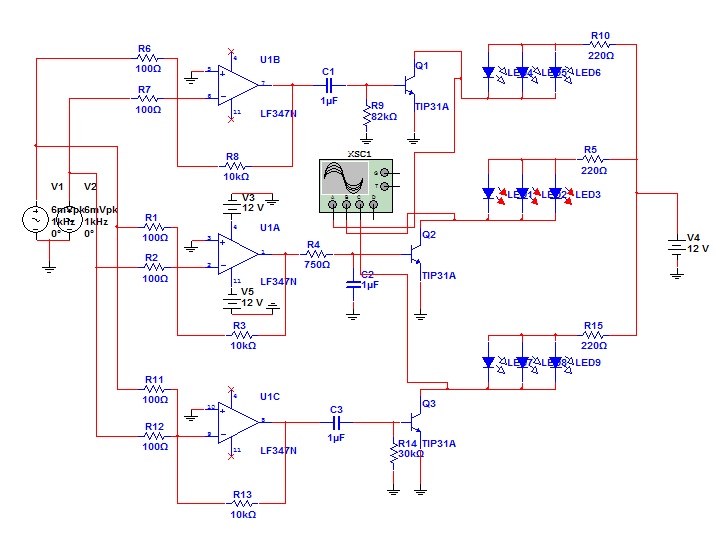
And it worked using an LF347N IC OpAmp and TIP31A transistor. I transpose them to the ultiboard to make the PCB.
This is what I get:


The green and blackish-green wire is the left & right input connected to my computer headphone jack. And two reverse supply of 9V battery each on pin 4 & 11.
Well, it didnt worked this time....
I dont know where I go wrong and my professor dont even know what to do "orz
So Im left with the community on this site to point out my mistake and help me with the construction of this circuit.
Thank you.
PS: Ive tried the simple circuit with just the transistor, resistor and LED. But the professor wont accept that.
Im currently making an LED sync with music for my school project. I decided to do this project because of a video on youtube and it really looks cool!
This is the circuit diagram I found and tried it on multism:
And it worked using an LF347N IC OpAmp and TIP31A transistor. I transpose them to the ultiboard to make the PCB.
This is what I get:
The green and blackish-green wire is the left & right input connected to my computer headphone jack. And two reverse supply of 9V battery each on pin 4 & 11.
Well, it didnt worked this time....
I dont know where I go wrong and my professor dont even know what to do "orz
So Im left with the community on this site to point out my mistake and help me with the construction of this circuit.
Thank you.
PS: Ive tried the simple circuit with just the transistor, resistor and LED. But the professor wont accept that.

")


