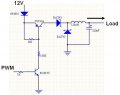
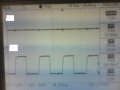
Hi, I am new with electronics, I am studying electronics at my college. Currently I am building a buck converter to convert 12V input to produce 10V at the output. The figure that I have uploaded is the input PWM signal (labeled 1) and the switching signal for the buck converter. My question is, are the PWM signal supposed to be the same with the switching signal for the buck converter? and can anyone give any suggestions on how I can improve the design of my circuit to obtain a better square wave shape. I am building the switching circuit for the buck converter using 2 BJTs.
- Oscilloscope settings : 5.00V/division, 25.0us/division
- Ch1: mean voltage = 4.32V, frequency 15.38khz
- Ch2: mean voltage = 9.38V, frequency = 204.1khz
Attachments
-
 62.4 KB Views: 62