Need help in 555 timer

Thread Starter

Feedback Circuit

Joined Mar 18, 2012
7
Hi,

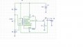
I am working on Resonant converter project, as a part of feedback design I have used 555 timer as the gate circuit, My circuit operating frequency is 50Khz and duty cycle is 50%, with these requirements I have designed 555 timer and I compared the gate pulse with the timer output, The timer frequency and duty cycle are good where as there are some slight shifts in output and pulse train is shifting

any one give some inputs please, I am attaching my Pspice file and wave forms document too
 

Attachments

Wendy

Joined Mar 24, 2008
23,429
A fairly normal 555 circuit. One glaring error though, you are powering a chip rated for 15VDC max with 22VDC. This will allow the magic blue smoke to escape.

A CMOS 555 is good for 18VDC, so no help there.

You want to build a VCO from all appearances. Could you show a bit more on the output?

I have made a several reverence you may find useful for 555s. Here are the links.

The 555 Projects

My Cookbook

LEDs, 555s, Flashers, and Light Chasers

http://forum.allaboutcircuits.com/picture.php?albumid=41&pictureid=308

http://forum.allaboutcircuits.com/album.php?albumid=41&pictureid=1233http://forum.allaboutcircuits.com/picture.php?albumid=41&pictureid=1233
 

Thread Starter

Feedback Circuit

Joined Mar 18, 2012
7
Thanks a lot, will there be any range for the control voltage range, actually my feedback output is 14v and that is going to the 555 timer control voltage, using the references from the post I have designed 555timer for 50% duty cycle using a diode and my freq is 50kHz, I got component value to be 200 ohm resistors and capacitor to be 0.288uF, but the simulation is not resulting in the 50% duty cycle and 50kHz..., so will there be any limit for the freq and control voltage ?
 

Thread Starter

Feedback Circuit

Joined Mar 18, 2012
7
I have designed timer for 50% duty cycle and 50K freq, I got component values to be 3.6k resistors and 4n capacitor, later I have fine tuned the values to get the desired 50K freq and 50% duty cycle,
but still the output wave form is shifting...:(
any one please give me some ideas to avoid pulse shifting, I am attaching newly designed 555D timer and output wave forms
Red colored is the original Pulse generator and Green colored is timer output
 

Attachments

Wendy

Joined Mar 24, 2008
23,429
Where is the red wave form coming from?

The 1st thought that occurs to me is if you have a VCO (the CMOS555) you could go all the way and make something called a PPL (phase locked loop).

You can use several ways to make a phase comparator, such as a XOR gate.

The VCO input of the CMOS 555 only works for a voltage range of 1/3>VCO>Vcc. At 1/3 Vcc it quits.

You will also find a CMOS 555 a different animal. It is close to a 555, but not quite the same.

BTW, the duty cycle will vary as the VCO voltage does. Each cycle is individual, one resistor for one duration and one resistor for off duration. I haven't verified this, so I could be wrong.
 
Top