Need help for a dawn/dusk LED circuit

Thread Starter

malaybiswas

Joined Feb 21, 2009
10
I am making a high intensity LED light panel for my aquarium. I got 15 1w Luxeon white LEDs rated at 350mA max continuous current and 3.42V forward voltage.

The LED driver specification is
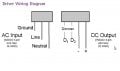
Input - 120 VAC 0.3A 31.9W
Output - 7.8-24.6 VDC 1050mA 25.5W

My basic circuit plan is to have 3 leg parallel circuit with each leg having 5 LEDs, so that I have 350mA current on each leg and need 17.1V for each leg of 5 LEDs.

The driver will be connected to power source with a timer to maintain a 10 hr photo period (or anything else that I want).

In this mix I would like to add a circuit that can control the intensity of the lights so that when timer is switched on intensity of lights gradually increase from 0-100% over 1-1.5 hrs time. Then they remain at full intensity till timer goes off. When timer goes off, the intensity decreases from 100-0% over 1-1.5 hrs time.

I can do basic circuits, but my knowledge on devicing advanced circuits is very limited.

Can anybody suggest me a circuit design to produce this effect for the specifications mentioned?

Any help is greatly appreciated in advance :)
 

Bernard

Joined Aug 7, 2008
5,784
Here is something to chew on.First thought was OP AMP integrator, but 1.5 hours seemed hard to reach, next was the thumbnail as a broad outline using an UP/DOWN counter feeding an Digital to Analog converter on to a Voltage Controlled Pulse Width Modulator, Driver & 3 MOSFET switches.
 

Attachments

Thread Starter

malaybiswas

Joined Feb 21, 2009
10
Here is something to chew on.First thought was OP AMP integrator, but 1.5 hours seemed hard to reach, next was the thumbnail as a broad outline using an UP/DOWN counter feeding an Digital to Analog converter on to a Voltage Controlled Pulse Width Modulator, Driver & 3 MOSFET switches.
Thanks a lot Bernard for sharing the circuit idea. I would need help deciphering how it works though (I am learning but my knowledge is still limited :))

Can you please break it down for me (which component/components will increase/decrease the intensity and how, how can I estimate how long it will take to move from 0-100% etc.)?

Second question...this circuit puts the driver in middle of the circuit. I bought the drivers to directly hook up to the AC source and was hoping that I would really not need to introduce any components between the AC source and the driver, rather have the circuit plugged in between the driver and the LEDs. Is that possible?

The 1.5 hour time period is just an example, it's not necessary that it needs to be that long. I just need it to be long enough to visually see the progress (1/2 hr, 45 mins, 1 hr should also do I guess)
 

Bernard

Joined Aug 7, 2008
5,784
Is what you call " LED Driver " a voltage regulated, adjustable power supply ? Any other inputs to it for control functions, ie, PWM ?
If you wish to leave " power supply " on full time , can eliminate SSRelay & 12V logic power supply[ replace with 12V regulator. Timer assumes 24 hr. clock controlling a NO un committed switch. The up/down counter with D to A converter generates a stair step voltage of 256 steps which is close to a voltage which rises from 0 to 5 V. The width of each step is set by the Oscillator period, adgustable with a POT from msec to a minute. 20 sec. gives 1.5 hrs. with 256 steps. At the top of the rise the Osc. is inhibited untill commanded by the Timer to start down. The trapezoidal voltage can then control a PWM, or an analog LED comtroller.
With shorter rise/ fall times might simplify this circuit with OP AMP intigrator.
 

Thread Starter

malaybiswas

Joined Feb 21, 2009
10
Is what you call " LED Driver " a voltage regulated, adjustable power supply ? Any other inputs to it for control functions, ie, PWM ?
If you wish to leave " power supply " on full time , can eliminate SSRelay & 12V logic power supply[ replace with 12V regulator. Timer assumes 24 hr. clock controlling a NO un committed switch. The up/down counter with D to A converter generates a stair step voltage of 256 steps which is close to a voltage which rises from 0 to 5 V. The width of each step is set by the Oscillator period, adgustable with a POT from msec to a minute. 20 sec. gives 1.5 hrs. with 256 steps. At the top of the rise the Osc. is inhibited untill commanded by the Timer to start down. The trapezoidal voltage can then control a PWM, or an analog LED comtroller.
With shorter rise/ fall times might simplify this circuit with OP AMP intigrator.

The LED driver I am planning to use is Xitanium LED-120A-0024V-10F. Here is a link to the datasheet. http://www.luxeonstar.com/xitanium-120v-drivers.pdf

The circuit I am planning is the 3rd wiring diagram at the bottom of the datasheet.
 

Bernard

Joined Aug 7, 2008
5,784
Might I suggest using the LED-120A-0024-10D ,as it has provision for dimming with a 0-10V control signal. Would be nice to have more information on dimming application.
 

Bernard

Joined Aug 7, 2008
5,784
One little tid-bit: LED driver LED-120A-0024-10D requires only 500 μA @ 0-10V for dimming. If using counter & D to A converter, a home built D-A works fine, slapped this short one together to prove point, using un selected parts 5 % 1/4 W. Linearity not too bad.
 

Thread Starter

malaybiswas

Joined Feb 21, 2009
10
Thanks Bernard. If I use LED-120A-0024-10D, how would your overall circuit change? Can you provide a modified schematic please?

A second one. I found these sunrise/sunset circuits.
http://ourworld.compuserve.com/homepages/Bill_Bowden/page6.htm#eyes6.gif

Can the 2 circuits be combined to get a sunrise and sunset combination? What would need to change for LEDs? One thing I guess would be MOSFET replaced with transistor.
 

Bernard

Joined Aug 7, 2008
5,784
With the two dawn to dusk ckts you could save all the OP AMPs and start over,probably would hard to hold full brightness for 7 hrs. with integraters.
Here' s modified thumbnail; no MOSFETs.
 

Attachments

Thread Starter

malaybiswas

Joined Feb 21, 2009
10
Bernard. I few questions on the circuit. What is the "Control" for? Is there a part # for it?

Besides I cannot read what you wrote for the connection between the 555 and up/down counter. What is that?

Finally, is the flip flop and control connected to 120V AC?
 

Bernard

Joined Aug 7, 2008
5,784
Now that we know that the DRIVER s output is dedicated to the 15 LEDs, we need the 12V supply to be connected to AC mains.Not shown is a fuse and switch on AC line. The TIMER assumes a one rev./day electric motor controling an isolated switch with ajuustable on time. The drawing is still just a verry rough block diagram to convey an idea. A brief run thru: When TIMER SW closes the OSC[ free running pulse generator ] is enabled, sending a pulse every 20 sec. to the COUNTER. The glitch between OSC & COUNTER was just a reminder that COUNTER I was reviewing , needed a neg. going edge to trigger. The COUNTER is two 4 bit binary up/down ICs to give 8 bits. The 8 outputs are connected to an 8 bit R/2R D to A converter. Each count raises the A/D output about 20mV, so 255 counts later the output is about 6V. A BUFFER voltage adjuster presents a high impedance to A/D , and provides the required 0-10V needed by DRIVER. When COUNTER reaches full count, 255,the OSC is stopped, LEDs remain at full brightness untill TIMER sw opens,when COUNTER starts counting down, decreasing brightness. CONTROL is a catch-all which may contain some gates and F/Fs to be determined when real parts are assigned. When COUNTER falls to "0" & down all operations stop.
 

Thread Starter

malaybiswas

Joined Feb 21, 2009
10
Thanks a lot Bernard for explaining in layman's terms (I needed that). I am really novice in this field and yet to get a hang on sofisticated controls like the 555 and D2A. But I am studying on these based on your idea and starting to get a hang of it.

As my understanding improves, I will try put a complete schematic and wiring diagram for this setup. I will publish it as I progress so that you can review it and help identify any errors.

Couple more questions at this stage:
1. I was also reviewing the wiring diagram for the Xitanium dimming driver. It has 2 dimming control nodes. That is confusing me as to how to connect the wiring from the buffer to 2 terminals of the driver.
Attached the wiring diagram for the driver from the datasheet for reference

2. In your diagram the connection from the driver to the AC main in not thru the timer (set to 10 hr). Won't this keep the LEDs on even after the timer switches off? I am asking this since the driver does not necessarily need a dimming voltage control (0-10v) to operate as mentioned in driver's datasheet below (highlighted in blue).

Also can you please check the specifications below and see if any changes would be required in your circuit to match the driver requirements?

1. The light output of the LEDs operated by the Dimmable Driver is controlled by
DC voltage applied to the control input leads (D1, D2).
2. The control device must be capable of accepting, or sinking, the DC current flow
from the Driver. The maximum under any condition is 500 microamps per Driver.
3. The control terminals of the Driver (D1, D2) are isolated from the power lines and
are suitable for use as Class II terminals. As many Drivers as desired for use with
the particular control device may be connected in parallel in a bus configuration.
The length of the bus, the wire size of the bus and the number of Drivers connected
on the bus must be configured so that the DC voltage drop as a function
of the resistance of the wire and the control current flowing does not exceed 0.2
volts for dimming controls. For controls used as a minimum/maximum, or hi-lo
2-level application, the maximum DC voltage drop must not exceed 0.5 volt.
4. If the control bus is opened, or if the control device internally opens the control
bus under some conditions, the voltage on the control bus will then be a
function of the ballast, which is 10V ± 0.5 volt. Maximum light output will be
delivered under this condition.

5. If the control bus is shorted either by a mechanical switch in the control or by
the circuitry of the control device, or inadvertently in the wiring, the current on
the control bus will be 500 microamps per Driver maximum. All Drivers on the
control bus will then operate at minimum light level.
6. As can be determined from the two above items, simple two-level operation of
the Driver can be achieved by proper usage and application of a simple
open/close switch on the control bus with maximum light being achieved when
the switch is open and minimum light when the switch is closed.
7. The Driver is intended for use with control voltages between 0 (zero) and 10
(ten) VDC. The control equipment must not impose a voltage greater than 11.0-
volt peak maximum on the Driver control terminals.
8. The DC control voltage should have a maximum peak to peak ripple (low and
high frequency ripple) not exceeding 10% of the average VDC. Short-term
transient voltage of the control devices must not exceed 14 volts.
9. Control equipment intended to control more than one Driver must be capable
of sinking the current supplied to the control bus by the maximum number of
Drivers specified for the control device. At any given level setting it must
maintain control bus voltage constant within a range of ±5% as the number of
Drivers connected to the control bus varies from a minimum of one Driver up
to the maximum number specified for the control device.
10.Drivers of various ratings (120V, 230V…) may be mixed on the same control system.
11.Since the control bus is Class II wiring, all control devices that are connected to
the power line must have proper isolation between the power line and the control
leads. Any control devices that are connected to the power line must have
UL approval/recognition as Class II equipment."
 

Attachments

Bernard

Joined Aug 7, 2008
5,784
It's late, but read the specs, just what you need. ' Picked out suggested ICs, will post them Friday after bowling.Rough draft of schematic is finished.
 

Bernard

Joined Aug 7, 2008
5,784
Suggested ICs: Up/dn counter, 4516 [ or 4029 same pins but no reset ]; FF, 4013 , 3 in nand gate , 74C10 or 4023, pins different ; schmitt inverter , 74C14 or 40106 ; OP-AMP , LM324. One each except for counter. D to A ladder should be available ,but no success in finding one. Easy to make, 1/8 or 1/4 W resistors select from 15-20 the closest 9 to 10 k and 7 to 5k.Other values OK if R 4.7k to 47k and 2xR. Note missing 555; a section of 74C14 used for pulse gen.
As shown last, power to DRIVER is always ON, LEDs OFF. A relay ,electromechanical or solid state can be added as control signal is available to control it. A commercial timer can be used, just add 120V relay to output.
 

Attachments

Thread Starter

malaybiswas

Joined Feb 21, 2009
10
Hi Bernard,

Not sure if you answered this question but I certainly did not understand if you did :)

I was also reviewing the wiring diagram for the Xitanium dimming driver. It has 2 dimming control nodes. That is confusing me as to how to connect the output from the buffer (LM324) to 2 terminals of the driver
Can you pls clarify?

Thanks for the part specs of the other components. I read about D to A. I think I should be able to make one at home.
 
Top