Need help designing a LED Necklace.

Thread Starter

Scott S

Joined Jun 25, 2010
14
Hello,
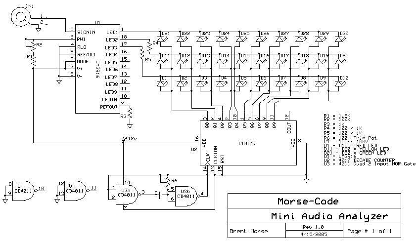
I am trying to design a LED necklace. The twist is that I am also trying to design the necklace so that the LEDs blink in response to music. I want to incorporate 16 to 20 blue and white LEDs in a pattern of: BWBWB..... ect. I found a few circuits that may help, but I'm not sure if they are practical for my purposes. http://www.electro-tech-online.com/...ync-music-sound-level-indicator-schematic.png
http://www.electro-tech-online.com/...ng-transistor-help-led_flasher_to_music-2.png

In the 1st link how would I incorportate a music input instead of a mic input. I am kind of new to electronics.
I want to power this with AAs and the music source will be a mp3 player.

Thank you for any and all help,
Scott
 

Bosparra

Joined Feb 17, 2010
79
I have so many questions.

Actually playing music is one thing, but where will the music come from? Will an external device be 'plugged' into the necklace or do you also want to store the music in the necklace? (I had to re-read this question a couple of times:D)

I reckon space is going to be a major issue, unless you put the circuit inside an enclosure that looks like a pendant or something?

Have a look at Atmel's website, you get some 8 pin micro controllers. With software you'll be able to eliminate allot of discrete components for blinking the led's.
 

Markd77

Joined Sep 7, 2009
2,806
The first circuit should work fine. It is by Audioguru.
For an audio input you should be able to get rid of everything to the left of C4 and play with the ratio of R8 and R9 to get it working. I think they could be replaced by a 200K potentiometer.
 

Thread Starter

Scott S

Joined Jun 25, 2010
14
I have so many questions.

Actually playing music is one thing, but where will the music come from? Will an external device be 'plugged' into the necklace or do you also want to store the music in the necklace? (I had to re-read this question a couple of times:D)

I reckon space is going to be a major issue, unless you put the circuit inside an enclosure that looks like a pendant or something?
An external device will be plugged into the necklace, it may be a mp3 player or phone. I was then going to plug the stereo cable into a splitter to i can listen to headphones/earbuds.

Will a splitter cut the power to the necklace circuit ? The pendant is really good idea. I was gonna put a minimal amount of AA batteries in a holder on the back. I was considering getting a size bigger holder, dividing off the un needed space, and stuffing the circuit in that extra space. I like your pendant idea better though.

The first circuit should work fine. It is by Audioguru.
For an audio input you should be able to get rid of everything to the left of C4 and play with the ratio of R8 and R9 to get it working. I think they could be replaced by a 200K potentiometer.
Thank you, i wasn't sure how to put in an audio input, as i am still new to electronics.


Thanks to both of you for your quick responses and good avice.
 

Thread Starter

Scott S

Joined Jun 25, 2010
14
Another question:
Being that there is limited space, is there anything in the first circuit, other than everything left of c4, that i can emliminate ?
 
Nice project,

several years ago I built several pairs of Gloves using " boxing under gloves" with ultra bright LEDs in the tips of the fingers. i powered them with 2 cr2032 batteries and sold many pairs of them to ravers at parties in south beach eventually I met my wife and she looked at my gloves looked at me and said " you and me are going to be friends forever !" we are about to have our first child in a few weeks and we are best friends......7 years later !


that being said.... build what your heart is telling you to build..

a few things i learned along the way with LEDS, outer wear, garmets, wires and power.....

#1 use wire from wired remote controlers from nintento or xbox.... it has a fiber inside the wire that prevents the wire from being broken if its pulled or experiances excessive motion. also it is very small wire strands which are more flexable. save yourself the grief !

#2 use " 3m emblem adhesive " to glue wire to leds so the insolator of the wire doesnt slide back and short, glue the outside of the wire to the led housing on the bottom.
this glue is perfect for all aspects of your project and will not let go. its also clear and sticks well to all materials.

#3 protect all your powered circuits from BODY SWEAT. it will short and corrode all your stuff in short ( no pun ) order. turns green too :)

#4 be carful if you use LION batteried, if they short the get VERY HOT and will burn your skin. it does happen to be the ideal voltage but....

try small camera batteries LION they have the current to keep up with high drain LEDS. some embeds will work on 3.3 volts.

#4 avoid using large current limiting resistors if possible, string LEDS to use available voltage from source otherwise battery run time on neckless device wil suck.

#5 research some of the circuits I have seen that drive LEDs in cellphone anttenas. they get power wirelessly and will give you some ideas about powering your neckless with a pulse coil in your pocket wirelessly. think RFID small pickup coils attached to led.

this is eventually how i powered my latest gloves. works within about 3 feet 200 khz pulsed am transmitter. think tesla coil.

#6 think bluetooth enabled microcontroller to link audio with your iphone or ipod

#7 keep in mind.... if your wearing the neklace, you will not see the flashes yourself, and no one else will be hearing the music that is creating the flashes in the neckless.
might be better to use the mic and try using audio freq discrimination to send some beats to part of the neckless and others to other parts. this way everyone else who does see the flashes can relate them to the music they are hearing.

#8 there are some toys out there everyone has seen.... they are little fans that spin and have led designs... if you study the waveform of these little circuits, you can see they are basically square wave tones with different duty cycles. and they are all COB construction.

also look at the spinning message signes for some ideas.

#9 Finally and most important !!!

DONT LET ANYONE BORROW YOUR NECKLESS IN A CLUB ! it will disappear just like a pair of my gloves did in las vegas. " yup they stayed in vegas "

Hope this helps .... ENJOY !

Oh and.... this is always true....

the brighter the better and use girl colors, like teal, grean, blue, purple, pink...

avoid red and yellow, it seems to piss people off.

if you must use red, place a blue very very close to it and it will appear purple when you move.

PS some guys in clubs dont like it when you draw attention to yourself and away from them, they will seek to beat the stuffing out of you and restuff you with your neckless. so make sure you have an off switch.

cheers !


here is an image of RGB leds that i bonded to thimbles for heat disipation, this is my latest project.... full color Gloves.

you can see the last thumb led sitting in the backround. i cant find a big enough thimble for my thumb.

you could do something similar using some kind of metal decorative item that you could string togehter.....

as far as which LEDS to use, there are some sites on the internet you can find that rate leds

check out .... http://www.candlepowerforums.com

for an idea.... basically i would start with a min led of say 30ma i would use a flat LED

get to know what the cones inside the led do.... its like the reflector of a regular photo bulb, you will have spots, med and floods available and anything in between...

you should use something around 60 degree flood.

If i was building it i would have to go with at least something around 200ma since everyone expects my creations to be very bright. but..... this would be tough, I would have to have a strong power supply. i havent been able to wirelessly power anything over 15 ma as of yet, but in a dark room they work ok.
I use cell phone batteries most of the time because they are easy to recharge and pop in and out of my holders easily , I have a few cell phones i use just for that purpose. i make holders out of thin plastic sheets of plastic, which i then glue small spring in as contact points. a small piece of tape holds the contact slider on the battery. its very reliable and almost water tite. some of the cell phone battierys put out 1200ma which would supply 10, 100 ma leds for about 1 hour. or... 20 50ma for about the same time.

learn the math :)

you must learn about SEPIC circuts.... this is a DC to DC converter, it allows you to use any battery voltage like say 1.5 volt battery and make whatever you need....say 2.8 volts which a common for some blue lights..

this is a common circuit that is used by the companies that make double aa flash lights. some of those white leds can require up to 3.8 volts. and at 3 volts they will not even light.

a sepic circuit will also drain almost all of the life out of a battery before it dies. it will start to pulsate.

also you can use the sepic circuit to make the leds "vibrate" which is very impressive in a dark enviroment. or you can modulate that power system easily with your audio source, just use a low power mosfet with a limit resister, on the gate and put that between your power output and your leds, put a small bias resistor around your gate to keep the leds from going completely dark. you will have to play with the values but thats the way i would do it.

with that circuit your getting very close to FM transmitter circuitry. the theroy is similar, modulate the output of an LC tank, which is basically what a sepic ouput stage is.

think about the shock you get if you touch a relay contact points when you engage and release the coil of the relay. its this emf collapse voltage spike that creates the possibility for transistion from one dc voltage to another. and the same kind of LC, tesla, LC tank ringing that makes a transmitter work.

if you study the basics of electrical and magnetic or gravitational resonance and connect the dots, you can see why i am trying to make the wireless led power thing work. its a little fringy but it works ! .... kinda.

you must learn about these things in order to make your neckless....

you need proper power,
proper heat disapation,
a smart power supply,
you must know how to drive an LED efficently to get the longest run time.
gotta modulate your leds with whatever source.
Gotta have fun doing it !

I cant tell you which leds to get becasue i just buy what i can find on Ebay, great source for very interesting 100watt led panels and other cool stuff. you can get a hundred 100 ma leds for around 10 bucks. any color your heart desires. i like teal ! kinda a traffic light green.

ok buddy good luck !

JEff
 
by the way , I would not use either of the circuits you have mentioned.
none of them is going to drive any led into considerable brightness.

try these circuits, you will not one of them is spacifically one i use, its a PWM driven SEPIC supply that works from a cell phone battery.

for audio you would need a frequency multiplyer circuit to be in its drive range but thats not hard.
http://www.whatcircuits.com/Category/power-supply-circuits/dc-to-dc-converter/

look at all these circuits, here is the 1 volt driver that is Great for small supplies, I have one that fits on a dime, and drives several blue leds with a single 1.5 volt cell....
not for long but it does.
 

Thread Starter

Scott S

Joined Jun 25, 2010
14
That problem that I'm having is finding a circuit that will make a necklace. Most are too bulky. Thank you for the help.
 

Thread Starter

Scott S

Joined Jun 25, 2010
14
I don't mean to ask a stupid question but, Why would i need a frequency amplifier ?
Also, what do you recommend for heat dissipation ?
 
Last edited:

Thread Starter

Scott S

Joined Jun 25, 2010
14
Can you describe how you made the wireless am tramitter to poer your gloves ? That sounds like a fix to my problems involving space.

Thanks for your time.
 

Thread Starter

Scott S

Joined Jun 25, 2010
14
I made a circuit. http://www.flickr.com/photos/51872883@N08/4769178237/
1. I was gonna use eithe 2N3904 or 2N4401 transistors. Which should I use, or is there a better option ?
2. Will this circuit work?
3. What can i do to make this circuit work, or work better.
4. Will speaker wire work for the circuit ? Solid or stranded ? what gauge ?
5. Would heat shrink help to make it more sweat proof ?
6. Would 1/2 watt resistors dissapate heat better than 1/4 watt ones.
7. Can you think of any other advice to give me ?

Thanks for your time. I appreciate it.
 

retched

Joined Dec 5, 2009
5,207
Ok, speaker wire COULD work, but I wouldn't start practicing bad practices ;)

The circuit MAY work depending on the current available from the battery and the particular types of components you use. I am worried about your transistor pinouts as a trigger for the flashing.

To work better, use better components.

Heat shrink will help sweat-proof the circuit.

1/2 watt resistors can dissipate twice as much heat as 1/4 watt resistors ;)

Keep on keepin' on. ;) Get yourself a breadboard and a handful of leds and transistors and dont be afraid to experiment before building your final project.
 

Thread Starter

Scott S

Joined Jun 25, 2010
14
I have updated the circuit to use 7.5 volts, that being 5AA or AAA. Someone pointed out that the leds were wired backwards, that I used the wrong symbol for a transistor and that I accidently used a wrong resistor value. The updated circuit schematic is attached.
Would a peak detector help with the sensitivity of this circuit ?
Also, what could I do to make it as responsive when the music is at listening volume, as when it is blairing ? I plan on using a splitter to listen to earpuds while having this on.

Thanks, Your time is appreciated
 

Attachments

BMorse

Joined Sep 26, 2009
2,675
If you build this using surface mount LED's, it would be easier to construct into a necklace type apparatus..... and if you use a microcontroller, and multiplex the LED's, you will only need 10 I/O's to control the 20 LED's, so you would basically only need 12 pins all together to control the all the LED's, which would make it less of a hassle trying to wire them all up individually..... you would basically need a UC that also has an ADC input for the audio interface part....

Do you have any experience with microcontrollers??

B. Morse
 

BMorse

Joined Sep 26, 2009
2,675
another option is to use an Audio VU meter IC (LM3914 or LM3916), but then the LED's would be sequenced, if you use 2 IC's then you can control all 20 LED's... possibly creating a VU Meter effect, have one go from left to right, and have another go right to left.....
or you can make it like a sequencer (This is not a real sequencer since it does not have filters for the different frequencies, but the effect is similar) You can use the circuit below, but only use 2 rows of LED's instead of the 3 rows that are shown, I believe you can get all these parts in a surface mount package (Hope you have good soldering skills and a pencil tip type soldering iron! :) ) so the circuit can still be made pretty small..... you might have to have a separate case for the power supply (batteries) which can be kept in a pocket or clipped onto the pants waist, and just have a cord that would plug into the "clasp" area of the necklace....


B. Morse
 
Top