Need help cannibalizing a Motion sensor

Thread Starter

pbalien73

Joined Dec 13, 2008
66
I have been working on a sculpture that I would like to have a simple light turn on as people pass. I have done this before with the safety lights but not with the smaller night lights. Another problem I have is that I need this to run on a 12volt dc system and the board I have is wired for 120AC. After a few hours of blindly trying to wire this thing up with 12 volt system I get the light to work but can't seem to get the IR sensor to function.

Questions:
1. Can this ever work or am I going about this wrong?
2. Is there a 12volt motion sensor out there that I can soldier inline?
3. Can I bypass the power supply reducer and wire directly to 12volt dc?
Thanks in advance!

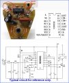
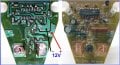
This is a picture of the board I have to work with if it helps in your answers
 
Last edited:

floomdoggle

Joined Sep 1, 2008
217
Try using a circuit from a motion detector light commonly found at your big box store. Or, just modify the light. What you have may work, with a lot of work.
 

Thread Starter

pbalien73

Joined Dec 13, 2008
66
Try using a circuit from a motion detector light commonly found at your big box store. Or, just modify the light. What you have may work, with a lot of work.
Thats what I have (from $8 nightlight) all I need is the ir to work with a 12volt dc power supply instead of the 120vac. Do I need a separate power supply for the ir sensor? How would you wire it up? Thanks for your time.
 

floomdoggle

Joined Sep 1, 2008
217
It depends on the circuit. If it runs on 12v DC you should have no problem. You could also try a rv or auto place, they use 12v as a supply voltage. Boats, too.
But as far as a circuit goes, I'm just the handyman, can't help you there. And be ready to fry some circuits. That's the fun stuff!
Dan
 

eblc1388

Joined Nov 28, 2008
1,542
Thats what I have (from $8 nightlight) all I need is the ir to work with a 12volt dc power supply instead of the 120vac. Do I need a separate power supply for the ir sensor? How would you wire it up? Thanks for your time.
In order to answer your question, one needs the datasheet of the HS0001 IC on the circuit board. I got it from a Chinese website, the data are in chinese and the IC operates at +5V supply voltage.

The image of the circuit board you've posted indicates a capacitor voltage dropper and so one would expect somewhere on the circuit board is some regulator circuitry to give a stable +5V supply. It could be the one circled or one of those diodes(zener). Can you read what is labeled on the circled component? Partial wordings is also OK. You don't have to remove them.

Therefore you need to provide an image of the back of this circuit board so we can "read" the copper trace and figure out what it really is. Make sure the image show clearly the traces.

If you just connect +12V to the board without checking, you might possibly destroy it.
 

Attachments

Thread Starter

pbalien73

Joined Dec 13, 2008
66
In order to answer your question, one needs the datasheet of the HS0001 IC on the circuit board. I got it from a Chinese website, the data are in chinese and the IC operates at +5V supply voltage.

The image of the circuit board you've posted indicates a capacitor voltage dropper and so one would expect somewhere on the circuit board is some regulator circuitry to give a stable +5V supply. It could be the one circled or one of those diodes(zener). Can you read what is labeled on the circled component? Partial wordings is also OK. You don't have to remove them.

If you just connect +12V to the board without checking, you might possibly destroy it.
Sounds like you know what your doing with this stuff. Thanks very much!!! I seem to have killed the board. Good thing I bought a few (figured I might kill one in the name of art)


Left circle part says DW1 and DW2. The black circled object on right says Q1
 
Last edited:

eblc1388

Joined Nov 28, 2008
1,542
Sounds like you know what your doing with this stuff. Thanks very much!!! I seem to have killed the board. Good thing I bought a few (figured I might kill one in the name of art)
Left circle part says DW1 and DW2. The black circled object on right says Q1
I just bluffing most of the times. Thanks for the clear photo. It works nicely.

After looking at the copper traces in the Xray image, I can now say with 99% certainty that two diodes DW1 and DW2 are in fact zener diodes. They are connected to the capacitive dropper bridge rectifiers via 1K resistors. One diode is dedicated for the two LEDs while the other one for the +5V regulation of the HS0001 IC.

So it will be easy for you just to connect +12V to those positions marked in the following diagram(image). For the sake of other forum users who might found this post months later, I also upload the HS0001 datasheet here.
 

Attachments

Last edited:

Thread Starter

pbalien73

Joined Dec 13, 2008
66
So it will be easy for you just to connect +12V to those positions marked in the following diagram(image). For the sake of other forum users who might found this post months later, I also upload the HS0001 datasheet here.[/QUOTE]

Wired and soldiered as you said. I got light from the nightlight (which I really don't want) and the IR sensor didn't turn off the light after 90 sec. it continued to stay on. I really just want the ir motion sensor to work with a 12volt light source. Cand I make my own board with the parts? How should I proceed? I don't want to burn this one out. Thanks for your time and trouble.
 

eblc1388

Joined Nov 28, 2008
1,542
Wired and soldiered as you said. I got light from the nightlight (which I really don't want) and the IR sensor didn't turn off the light after 90 sec. it continued to stay on.
Don't give up just yet.

Have you replaced the whole circuit board back into their original casing when you did the test? There are light barrier and IR filter covering the the IR sensor which most likely is mounted on the casing. Without this filter, the whole circuit will not work. You have to reassemble the whole thing and let the two extra battery connecting wires out in a gap of the casing somewhere.

I really just want the ir motion sensor to work with a 12volt light source.
Yes. I know what you wanted. But that's the second step down the line. What we need to do first is to make the night light works as it should on DC 12V instead of 120V AC.

When you have achieved that, then we can use it to drive a 12V light.

The final step is to adjust the ON timing of the 12V light upon detecting personal movement.

Cand I make my own board with the parts? How should I proceed? I don't want to burn this one out. Thanks for your time and trouble.
Of cause you can. But it will not be any simpler that this one. Just looks at the diagram I posted in my first reply post. That is the schematic drawing you'll need to connect other parts up to use this IR detector.

Unless you can buy a ready made one for your special purposes, I don't think there is any easy way out.

There are alternative circuit designs that don't use IR but use instead a single LDR which detect slight change in ambient light level as people walk pass and it can also suit your requirement.
 

Bernard

Joined Aug 7, 2008
5,784
Looks like the sensor is a "flake thermistor tied to a fet "?? It detects body heat or rather contrasts in heat received. Might be able to just use sensor,comparator and of course a 555. With power applied it would be interesting to monitor voltage at junction of 2.2k&22k to gnd.
 

Thread Starter

pbalien73

Joined Dec 13, 2008
66
Looks like the sensor is a "flake thermistor tied to a fet "?? It detects body heat or rather contrasts in heat received. Might be able to just use sensor,comparator and of course a 555. With power applied it would be interesting to monitor voltage at junction of 2.2k&22k to gnd.
Sounds like what I want to do. Can you give me drawing of how wire (in english:))
 

Bernard

Joined Aug 7, 2008
5,784
My suggestion is to stick with present ckt. board with eblc1388's help,seems you are close. A new ckt. has its own growing pains and without a sensor in hand to "play " with could lead to many false starts. Murata Mfg, IRA-E 712ST3, Newark part # 97K1949 @ 45.24 looks much like you have. PIR has multiple meanings: Pyroelectric Infra Red,Passive Infra Red . Google lists many motion detectors,most or all would need some interfacing.
 

Thread Starter

pbalien73

Joined Dec 13, 2008
66
Don't give up just yet.

Yes. I know what you wanted. But that's the second step down the line. What we need to do first is to make the night light works as it should on DC 12V instead of 120V AC.

When you have achieved that, then we can use it to drive a 12V light.

The final step is to adjust the ON timing of the 12V light upon detecting personal movement.
Ok, it works to turn on the two LED's now how do I get it to run the 12volt light?
 

eblc1388

Joined Nov 28, 2008
1,542
Ok, it works to turn on the two LED's now how do I get it to run the 12volt light?
I'm glad it finally work.

You need to tell us what type of 12V lamp(s) you are trying to use, like current or wattage if you know about it. Or attach a photo showing the 12V light.

Depending on the current, you might be able to drive them directly using the transistor inside the Night light unit.
 

Bernard

Joined Aug 7, 2008
5,784
Just found interesting item from Goldmine Electronics , PT # G4567 $4.95.PIR operating on 9V battery with instructions to add relay[or lamp ]. Sale ends 1-1 09. For backup just incase. I have to have one.
 

Bernard

Joined Aug 7, 2008
5,784
The Dec. 2008 issue of 'Nuts and Volts " has an interesting article, Build A Dog Detector, covering several motion detection schemes.
 

Bernard

Joined Aug 7, 2008
5,784
Just found interesting item from Goldmine Electronics , PT # G4567 $4.95.PIR operating on 9V battery with instructions to add relay[or lamp ]. Sale ends 1-1 09. For backup just incase. I have to have one.
I now have one & it catches me every time I entor " library ".
 
Top