
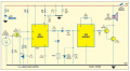
The circuit below was posted in another thread, and is apparently a popular "project" for engineering students in India. Although the shematic is quite ubiquitous, it may have come from the attached report.
I have no interest in building the complete project, but I have breadboarded the 555 portion as drawn, including the piezo trigger. My understanding of the claim made in the report is that the 555 latches high on the first trigger pulse from the piezo, but my breadboard does not do that. When I put pressure on the piezo, pin 3 of the 555 goes high, but does not latch high. As soon as the pressure on the piezo is relieved, the output of the 555 goes low.
My question is whether the schematic does have a "latch" function designed in (which means I have a construction error) or not; if it does, would you please explain the latch function?
Thanks.
Attachments
-
602.9 KB Views: 806
-
 216.4 KB Views: 309


