Piezo speaker driven by UC3845 on 30 Volts SMPS Power Supply?

sghioto

Joined Dec 31, 2017
8,737
The 555 oscillator isn't configured correctly and the base resistor on the BC547 is way too small.
The ZD15 volt zener is shown in backwards on the schematic and the regulator chips are missing important input and output capacitors.
The LM350 is way over kill for the 555 oscillator.
Don't see the need for the 30 volt regulator, run the mosfet driver which needs help on the 32 volt supply.
 
Last edited:
Piezos have a significant capacitance that requires to be both charged and discharged. Although you do have a resistor in parallel, it won't discharge fast enough and cause static power consumption.
A best approach is to use a low side Mosfet driver. Even better, some SMPS chips like the UC3844 have both an integrated oscillator and a powerful totem-pole output, and thus you can build your circuit with a single 8-pin chip. With its feedback grounded, it will give a nice 50% duty cycle square wave, which your circuit won't provide.
Heck, your 555 as shown, it won't oscillate at all.
 

AnalogKid

Joined Aug 1, 2013
12,232
Also, the 555 needs serious power supply decoupling because of current spikes in its output stage.

Also, why does one of the LM350's have two adjustment pots in parallel?

And - Reference Designators !!!

ak
 
Last edited:

Thread Starter

cmpx

Joined Oct 23, 2021
55
Thank you all for the replies and avices.

>> Don't see the need for the 30 volt regulator, run the mosfet driver which needs help on the 32 volt supply.

I need to have secound LM350 as voltage regulator to adjust piezo intensity?

I understand I made mistakes I am starting to make the circuit from begin.

>>A best approach is to use a low side Mosfet driver.

Yes I agree.

Are IR2104 or IR2111 good choice for mosfet gate drivers?

I think both of them can be connected to +32V directly because they have Fully
operational to +600V?

>>Even better, some SMPS chips like the UC3844 have both an integrated oscillator and
a powerful totem-pole output,

I accept your advice. What the LM350 output voltage should be acceptable for
powering thh UC3844?

>>Also, why does one of the LM350's have two adjustment pots in parallel?

To have more precise voltage range from LM350? I don't have 5K pots only 10K pots?
 
Last edited:

Thread Starter

cmpx

Joined Oct 23, 2021
55
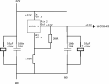
Please if somebody could tell me is my LM350 circuit diagram correct?

This LM350 circuit is to be used to supply +12V output to UC3845?
1.png
 
With that 32 volts into the regulator and the 12 volts out, you are dropping 20 volts in that regulator. At 50 milliamps that is producing ONE WATT of heat. SO HEAT sinking is needed.
 

Thread Starter

cmpx

Joined Oct 23, 2021
55
I understand that UC3845 i much better for driving a piezo speaker.

I drew two LM350 diagrams one I already shawn is to supply +12V for UC3845 and for IR2104
ic circuits.

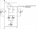
The secound LM350 diagram is for supplying two IRF3205 mosfets? I undestand that
I will need to supply a large heat sink for it.

Please if somebody could tell me is my secound LM350 diagram correct?

EG 2156.jpg
 
Last edited by a moderator:

Thread Starter

cmpx

Joined Oct 23, 2021
55
I am using two 10K potentiometers in parallel to get a final resistance of
5K, since those are the only ones I have in my workshop at present.
I can achive fine voltage tunning with them.
 

Thread Starter

cmpx

Joined Oct 23, 2021
55
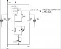
Here is corrected diagram with a single 10K var potentiometer parallely connected with fixed 10K resisEG 2156.jpgtor?
 
Last edited by a moderator:
There was nothing WRONG with the original circuit, although it may be a bit more tedious to adjust. " Funny Looking" does not make it wrong at all. It would work quite well.
 
Top