nand circuit issue

Thread Starter

duxbuz

Joined Feb 23, 2014
133
hi

When i create this circuit I get strange results using the logic probe.
http://i1025.photobucket.com/albums/y319/duxbuz/nandcircuit_zps0f040b17.jpg

The inputs for the Nand are not low whilst the switches are not pressed, the logic returns no reading.

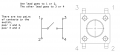
I am using tactile switches. Is this the issue? I dont know much about switches but I can only think that i am using the wrong type.

If i remove switches wire up inputs to ground or supply i get expected readings.

Anyone help please?

Thanks
 

bertus

Joined Apr 5, 2008
22,278
Hello,

What kind of switches are you using?
Are the switches like these?


Those are tacticle switches with 4 pins.
There are two pairs of pins, with the switch in between.

Bertus
 

Attachments

Thread Starter

duxbuz

Joined Feb 23, 2014
133
Thanks

I seem to have it wired ok.

When I press the buttons i get the expected high logic.

Its when they are not pressed that i dont get any reading.

I thought that the wires with the resistors on were there for this reason, to complete the circuit regardless of the state of the switch. But this doesnt seem to be the case.
 

tracecom

Joined Apr 16, 2010
3,944
The resistors are called pull-down resistors, and are intended to keep the inputs to the NAND gates low until the button is pressed. My guess is that you have the resistors on the wrong side of the switches. Check your assembly again to be sure that the resistors go directly from ground to the NAND gate inputs and not through the switches.
 

Thread Starter

duxbuz

Joined Feb 23, 2014
133
Hi

I have looked it over again. I have looked at the original which also had a photograph so a novice can see the connections.

I think mine is correct but it still wont give a low signal on the A and B input when switches are in circuit and not active

I took a picture to see if it can show that it is all in order:


http://i1025.photobucket.com/albums/y319/duxbuz/MV900F/SAM_0541_zpsd5ec8f26.jpg
(ignore the random green wire in pin 33)

http://i1025.photobucket.com/albums/y319/duxbuz/MV900F/SAM_0542_zpsf732796d.jpg

fuller picture showing top rail
http://i1025.photobucket.com/albums/y319/duxbuz/MV900F/SAM_0544_zps2a615b23.jpg


Its driving me nuts, cant move on to next part till it i figure it out!

Are these switches really ok, its the only thing i can think that is wrong.

Although kinda hoping someone will see the picture and see an obvious error.
 
Last edited:

sheldons

Joined Oct 26, 2011
613
your resistors need to go to supply and the input of your nand and the switch needs to pull the input of the gate low in order to light your led with the switch closed ....just as an example if you were using a 4093,sc pin 1 and 2,10k resistor from 1 and 2 to supply ,switch between 1 and 2 to ground and pin 3 will swing hi with the switch operated and low with the switch open.....
 

tracecom

Joined Apr 16, 2010
3,944
It looks to me like the resistors on pins 1 and 2 are in the right place. They are 10k, 1%, right?

What is that on pin 3? Is it a 1.5k resistor going to ground?

Pin 3 is the output and should not be tied to ground. The original schematic shows a 1k and an LED on pin 3, which would serve as an indicator of the state of pin3: LED on = high, LED off = low.
 

tracecom

Joined Apr 16, 2010
3,944
Okay, let's back up. Here is the truth table for a NAND gate.


The only time pin3 should be low is when both switches are operated. What is yours doing?
 

Attachments

Thread Starter

duxbuz

Joined Feb 23, 2014
133
Hello

Yes I understood the truth table

My circuit works if I change the resistors. I remove the 10K resistors and replace with 1.5k.

I presume this is not a good idea. But it works.


http://i1025.photobucket.com/albums/y319/duxbuz/MV900F/SAM_0545_zps4e03f52e.jpg

both switches off
http://i1025.photobucket.com/albums/y319/duxbuz/MV900F/SAM_0546_zps18f65aec.jpg

both switches on
http://i1025.photobucket.com/albums/y319/duxbuz/MV900F/SAM_0547_zpsa972c4e2.jpg

bit too tricky taking one handed photos to do all permutations

Thanks

p.s. the LED has never seemed to light in any of the circuits I presume it doesnt receive enough power
 

kubeek

Joined Sep 20, 2005
5,795
the difference you have is that the original circuit uses 74HCxx series chip, while you are using the really old 74xx series. These chips require quite substantial current to be pulled from the inputs to register it as a low level, according to datasheet this current is up to 1.6mA. This is why it works correctly with 1.5k pulldowns but not with 10k.
 

kubeek

Joined Sep 20, 2005
5,795
I dont think I would have guessed it without the photos, the original TTL (non-cmos) chips are quite rare nowadays, and I doubt they are still being manufactured. Normally you would use a HC or HCT versions, as these are the most commont that you can buy.

Ok I checked on farnell and a 7400 costs about three times more than 74HC00, so I guess you can still get them, or at least some from that series, but I think they will be new old stock and not manufactured anymore.
 
Top