Musical Instruments: Tube Tape Delay distortion

Thread Starter

omaroski

Joined Jun 19, 2008
34
My brother bought this thing, it's a Copicat Echo and need to be fixed cause it outputs a distorted sound.

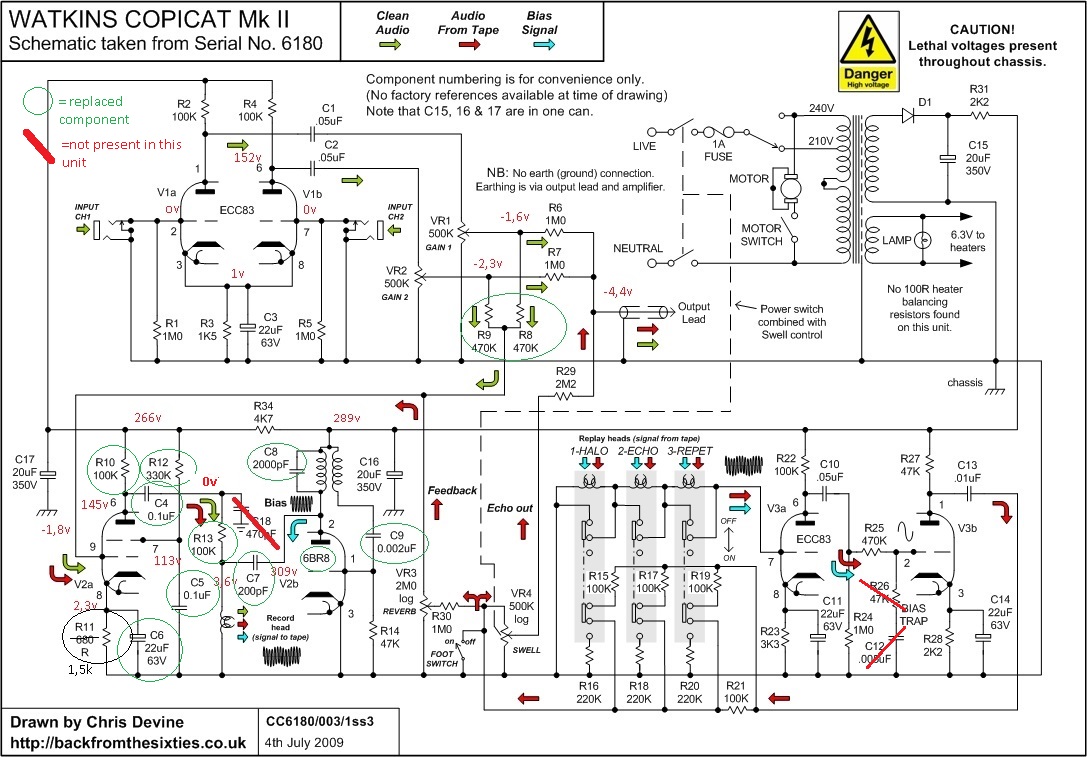
I took this schematic as a reference, it's not the same but it looks very similar:


Heads seem a bit oxidized but in good shape. I cleaned and demagnetized them before start playing.

The direct out after first stage was really clean sounding but the delayed part was not...First thing i did was to look for biasing and found this 50 khz signal. Then i swapped tubes, only 12ax7 cause 6br8, the one that belongs to recording and biasing stage, is not as common. Looked for bad solder joints but everything seem to be ok on the board.

Then tried less conventional methods, i cut the recording head wire and made an output to my guitar amplifier to see what's going into recording. The sound was heavily distorted.

Then soldered back everything again and played a signal (first a sine then my guitar) directly to the record head (ugly ugly thing i know...) with bias osc stage always feeding the rec head. I found that it was distorting again but not as much as with first test.

Now i just ordered a 6br8. While waiting, do you have any idea or suggestions about any alternative and less obvious things (to me) that may be causing the distorting sound?

Later i measured the bias voltage with my oscilloscope and it was something like 380v p-p, is that ok?

Thank you
Omaroski
 

tubeguy

Joined Nov 3, 2012
1,157
Later i measured the bias voltage with my oscilloscope and it was something like 380v p-p, is that ok?
I've never worked with recording heads but 380v pp seems too high.
Does the recording head show continuity/resistance?

Here's some info on biasing:
View attachment Recording Head Bias.pdf

Edit: If you inject a signal at the grid connection for the playback heads do you get a clean sound?
 

chuckey

Joined Jun 4, 2007
75
have you checked the .1MF feeding the record head? If its leaking it will magnetized the head, further then the bias can compensate for and reduce the HT to the Valve.
Frank
 

Thread Starter

omaroski

Joined Jun 19, 2008
34
Thank you all for replies!

I sent an email to mr. Watkins even if the circuit is really simple and not hard to track. At least i'll be able to say if someone has been modding it.

I checked heads for continuity and no, they are not shorted.

I wired a pot to make the bias adjustable (i read the linked pdf about overbias condition) but it didn't fix the problem.

have you checked the .1MF feeding the record head? If its leaking it will magnetized the head, further then the bias can compensate for and reduce the HT to the Valve.
Frank
No, it doesn't look to be leaking. It appears in good conditions.
 

tubeguy

Joined Nov 3, 2012
1,157
I sent an email to mr. Watkins even if the circuit is really simple and not hard to track. At least i'll be able to say if someone has been modding it.
I Googled Copy Cat and repeatedly came up with the same schematic you posted. Maybe someone was working on it and messed it up.
What is different ??
 

Thread Starter

omaroski

Joined Jun 19, 2008
34
Hello, sorry for not replying but i was waiting for the new tube to test! Unfortunately it's not a tube replacement related problem.

If i inject a signal into the grid of the playback tube i get a clean sound.
The transistor is a germanium Mullard OC200 connected at the output as an emitter follower. The only big difference is the transistor at the output and the fact that there's no bias trap to filtrate the bias signal in playback.

I tried to change 680 ohm cathode resistor with 1,5K in the pentode stage cause on tube transfer characteristic such an value would bias the grid at -2v causing to work in a non-linear region. The signal is a little bit cleaner now that is biased at -3,7v and i could realize that the problem is not really distortion but some kind of very fast modulation more audible when playing high pitch notes.

Do you have any idea?
Thank you
Omar
 

tubeguy

Joined Nov 3, 2012
1,157
You may have tried this stuff, but here are some ideas.

Check the values of the resistors. Double check for leaky caps (meaning DC leakage if that wasn't clear)

You have verified the bias oscillator is at 50 khz correct ?

Run a 1khz test tone in.
Measure and verify the 1khz signal looks OK (not Clipped) out of the pentode, and the 50khz bias signal looks OK. Check the mixed signal going into the recording head. It should have the 50 khz bias signal riding on the 1khz test tone. Check for excessive clipping if it's possible.

If any of the coupling capacitors are ceramic's replace them with a better quality cap.

Verifiy the power supply voltages are good and the DC is clean without excessive AC ripple.

You said it wasn't a tube problem. Did you get the new tube and try it anyway ?

If nothing shows up you could post voltages found, especially around the record circuit. Maybe more ideas will present themselves.

Good Luck !!
 

JohnInTX

Joined Jun 26, 2012
4,787
If i inject a signal into the grid of the playback tube i get a clean sound.
If all the electronix check out, make sure that the tape itself is running smoothly. A sticky belt, bad motor or anything else that makes the tape jerky across the head(s) will also distort the sound. It doesn't have to be much or even visible. Old cassettes sometimes would start binding and squeaking audibly. Those mechanical vibrations would also sometimes cause tape vibration/high frequency jerkiness over the head and what started as a mechanical squeak would be heard in the speakers.
 
Last edited:

thatoneguy

Joined Feb 19, 2009
6,359
Is there anything like a head mounting/alignment screw that's loose?

I know it's not stereo, but may be something adding a bit of distortion, but not as much as you are stating.
 

Thread Starter

omaroski

Joined Jun 19, 2008
34
You may have tried this stuff, but here are some ideas.

Check the values of the resistors. Double check for leaky caps (meaning DC leakage if that wasn't clear)

You have verified the bias oscillator is at 50 khz correct ?

Run a 1khz test tone in.
Measure and verify the 1khz signal looks OK (not Clipped) out of the pentode, and the 50khz bias signal looks OK. Check the mixed signal going into the recording head. It should have the 50 khz bias signal riding on the 1khz test tone. Check for excessive clipping if it's possible.

If any of the coupling capacitors are ceramic's replace them with a better quality cap.

Verifiy the power supply voltages are good and the DC is clean without excessive AC ripple.

You said it wasn't a tube problem. Did you get the new tube and try it anyway ?

If nothing shows up you could post voltages found, especially around the record circuit. Maybe more ideas will present themselves.

Good Luck !!

Yes i tried the new tube but the problem is always there.

For leaking caps i don't have a proper high voltage instrument to measure them, i can only check for unwanted DC voltages not filtered out. I'm looking forward on how to get such a instrument or alternative methods. I can always change all the caps in the circuit one stage at time because they are not so many.

Yes i sent and measured the test signal over the 50Khz bias and i can see the 1khz riding the high frequency, however the 1khz is barely visible cause of the amplitude difference between the two signals.

Today i will do my homework and post the voltages measured in circuit.

Wow and flutter?
Quote:
If i inject a signal into the grid of the playback tube i get a clean sound.
If all the electronix check out, make sure that the tape itself is running smoothly. A sticky belt, bad motor or anything else that makes the tape jerky across the head(s) will also distort the sound. It doesn't have to be much or even visible. Old cassettes sometimes would start binding and squeaking audibly. Those mechanical vibrations would also sometimes cause tape vibration/high frequency jerkiness over the head and what started as a mechanical squeak would be heard in the speakers.
i did suspect something related to tape transport, heads or motor. It really looks like a flutter echo. I used isopropyl alchol to clean tape path, rubber cleaner for the capstan, because it is sorrounded by a rubber, and demagnetized everything. It is a very rough design, the motor shaft coming out from the chassis is the capstan, no belt drive.

I have some experience with tape machines because i use them for recording sessions from time to time, however i never opened one to fix, i only do the basic alignment procedure.

In practice there is an arm with two rollers and a magnet for erasing in between, the arm is kept in tension by a spring. I tried to replace it too but i didn't have one similar around so i put a stronger one which seemed to mantain the arm in a more stable position. However i didn't solve the problem.

What do you think?

Is there anything like a head mounting/alignment screw that's loose?

I know it's not stereo, but may be something adding a bit of distortion, but not as much as you are stating.
Yes there are brackets holding heads down but nothing to align height, azimuth etc.
 

Thread Starter

omaroski

Joined Jun 19, 2008
34
So here are all the dc voltages with no signal applied, i've found the schematic redrawn on the web, mine differs because there's a Mullard OC200 silicon pnp transistor in the output stage as a voltage follower, in the schematic just imagine the OUTPUT connected to the base of the transistor. Also, there's no bias trap.
Circled green components are those i replaced, in the pentode stage i replaced the 680 resistor with 1,5k because as said it seemed strange to me looking at the datasheet characterics (maybe wrongly because there's the screen grid that acts like compressing the grid curves when there's signal at the input?). The cap in parallel with cathode resistor was replaced with 50uF cause i didn't have a 22uF.
Here it is:


Uploaded with ImageShack.us

Now the waveforms with 1Khz sinewave at the input:


How does it sounds? Here it is, the shortest delay setting:


https://soundcloud.com/omaroski/echo_problem

All the voltages measured to gnd, the -1,8v is measured with respect to ground too. It seems strange to me. Also the input waveform at the pentode grid looks distorted. What do you think about? I also did the following test to exclude the 12ax7/ecc83 input stage, i disconnected the circuit at the pentode control grid and injected the guitar through a clean booster.
 
Last edited:

thatoneguy

Joined Feb 19, 2009
6,359
Can you put the scope's V/div and time/div on each photo?

Maybe crank the horizontal up a bit so a more clear waveform appears on the mixed bias and signal image.

With no input, do the signals match what is shown on the schematic (tape bias system)?
 

Metalmann

Joined Dec 8, 2012
703
Do you have pics of the machine? It reminds me of my old Echoplex from the 60-70s. The recording sounds like the speed may be too high, or another setting isn't right.:confused:
 

tubeguy

Joined Nov 3, 2012
1,157
Great info posted so far!!
But please post info and adjust the displays as thatoneguy suggested.

What is the resistance of the recording head ?

My concern is the 380v p-p bias voltage measurement you posted earlier.

And - mechanics is the capstan roller soft (should give a little when pressed)
or hard as a rock ? :rolleyes:
 
Top