Multiple Output Flyback with LT8306 No-Opto Isolated Flyback Controller

Thread Starter

Ngaru

Joined Jun 26, 2024
4
Hie
I want to design a isolated flyback using LT8306 with 2 outputs. I am simulating with LTspice and I am having some issues with the output voltage. I want two different outputs of 20V and 5V from an input of 6V to 26V but instead I'm getting the same output voltage of 20V despite having different secondary windings inductance values. Because I did not know what the problem might be I decided copy a design that is already presented in the LT8306 datasheet and it suppose to give different voltage output but when I run it I'm getting also getting the same voltage output for both outputs.


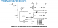
Below is a screenshot of the design I copied from the LT8306 along with the LTspice model
 

Attachments

Papabravo

Joined Feb 24, 2006
21,343
Could it be because you have the same identical netname for BOTH outputs?!
Could it also be that you failed to couple L1 & L3?!
And....if I fix both of those problems
There is something odd about the simulation. The outputs are going to infinity.

1719441435328.png

Dinner is ready so I'll be back later.
 
Last edited:

ronsimpson

Joined Oct 7, 2019
3,263
I found two errors. Rename one of the two Vout to Vout2. You have both outputs tied together.
K1 L1 L2 1 change to K1 L1 L2 L3 1 the K statement does not include L3.
 

Papabravo

Joined Feb 24, 2006
21,343
It is a minor point, but you don't technically have isolation if you connect the grounds on both sides of the transformer together.
 

Thread Starter

Ngaru

Joined Jun 26, 2024
4
It is a minor point, but you don't technically have isolation if you connect the grounds on both sides of the transformer together.
Thank you. And what exactly do I need to do to have isolation . How do I connect the output on different ground in LTspice.
 

Papabravo

Joined Feb 24, 2006
21,343
Thank you. And what exactly do I need to do to have isolation . How do I connect the output on different ground in LTspice.
You need to create an "isolated ground" for either the primary side or the secondary side, but not both with a very large DC impedance, e.g. 1GigaOhm and a very low AC impedance at high frequency, e.g. 0.1 µf. The example below is for an isolated ground on the secondary side of the transformer. Connect all "Grounds" on the secondary side to the net ISO_GND. Connect all "Grounds" on the primary side to Global Node 0 using the default triangle symbol
1719465293490.png
 

Papabravo

Joined Feb 24, 2006
21,343
You made a couple of mistakes:
  1. You did not connect the ISO_GND to the two secondary circuits correctly
  2. When probing voltages with respect to the ISO_GND, you have to Left-Click and Hold the mouse button, while you move the probe over to the ISO_GND that the output is supposed to be measured with respect to
1719500223562.png

I did fix the schematic for you and rearranged it to show up a bit better
 

Attachments

You need to create an "isolated ground"
SPICE is grumpy about isolated grounds. It has caused much confusion trying to teach how to do isolation.
The 1Gohm and 1pF across isolation is not real life any way. Now you must show people how to measure voltages on the isolated ground. If you really want to get closer to real life add inter winding capacitors to each winding in the transformer. And leakage current between windings. And add in resonant frequency of the windings. While we are at it I usually add in the L&R hiding in the capacitors and the C&R hiding in each winding. Too complicated for most people.
This design just needs to work (with or without isolation). This is what SPICE is all about. Trying changes and seeing what happens. I connect all the grounds together and don't worry about isolation in SPICE.
Actually, making it isolated is what you do when the PCB is made.
 

Papabravo

Joined Feb 24, 2006
21,343
SPICE is grumpy about isolated grounds. It has caused much confusion trying to teach how to do isolation.
The 1Gohm and 1pF across isolation is not real life any way. Now you must show people how to measure voltages on the isolated ground. If you really want to get closer to real life add inter winding capacitors to each winding in the transformer. And leakage current between windings. And add in resonant frequency of the windings. While we are at it I usually add in the L&R hiding in the capacitors and the C&R hiding in each winding. Too complicated for most people.
This design just needs to work (with or without isolation). This is what SPICE is all about. Trying changes and seeing what happens. I connect all the grounds together and don't worry about isolation in SPICE.
Actually, making it isolated is what you do when the PCB is made.
It is hard to argue that point, which is why I said in post #5 that it was a minor point. You could also have a DC source that would produce an actual voltage difference between ISO_GND and global node 0.
 
Top