MCP2221A

Thread Starter

cmartinez

Joined Jan 17, 2007
8,304
Microchip's MCP2221A is one of the IC's that I use the most. It's basically a USB to UART converter, and I've been using it for years. In fact, that chip is present in virtually all of my projects.

The chip in question that I've been using is the 14DIP version of it. It's formal denomination is the MCP2221A-I/P.

Anyway, for a recent project I decided that I've had enough of using the big and bulky 14DIP package, and bought several 14-SOIC sized chips. Those chips have EXACTLY the same pinout and supposedly have the same circuit in them. The only difference being that the latter is a smaller, SMT version of it.

Well, I put together a small circuit and when I plugged it into one of my computer's USB ports, an error is flagged and reports a 43 "device description not recognized" or something like of the kind. I then thought that maybe it had something to do with my desktop running on Windows 10, so I plugged into my laptop that runs on Windows 11 ... same problem. Again ... I looked online for the most recent driver for the chip, downloaded and installed it, and the result was the same.

At first I thought that I had burned the damn thing when I soldered it to the PCB, so I de-soldered it using a heat gun and very carefully installed a brand new one, this time making extra sure that the soldering temp never exceeded 435°F (224°C) ... I have never damaged a chip when working at those temperatures .... It didn't make a difference. When I plugged the thing to my computer the same error was reported.

What gives ??? I made extra extra sure to use the exact same circuitry and layout for the 14DIP package when I decided to use the 14-SOIC version and things aren't working out ... Is it possible that a given IC performs differently depending on its type of package?
 

jiggermole

Joined Jul 29, 2016
161
You're right, I'm not seeing anything in the datasheet to explain. All that information is in flash so unless they flash the memory at the factory with different information, than it shouldn't matter which package is used. Kind of curious if you find anything.
 

Poyntat

Joined May 24, 2022
60
I too have combed the data sheet hoping to find a reference to a silicone or firmware revision but there appears to be no ‘logical’ reason for the difference in behaviour.
I know you are not going to like my next question but it’s unavoidable.
Have you thoroughly checked your new pcb design to ensure that changes in pcb layout to accommodate the smd package hasn’t introduced a cross coupling, grounding or power supply decoupling issue.
 

Thread Starter

cmartinez

Joined Jan 17, 2007
8,304
Found the culprit...

The first thing I did was go, again, through each and every single pin connection, as suggested. And I found, again, nothing wrong with the way I did things.

Then, as per Spook's suggestion, I studied the breakout module's schematic and found one inconsistency, which is the use of a 0.47 µF bypass capacitor at the VUSB pin. My circuit lacked said capacitor. But the thing is that ALL of my other circuits lacked said capacitor too and I never had a problem. But I installed said capacitor (and plan on always including it from now on) and still the damn thing didn't work.

So, out of a hunch and a little desperation, I decided to swap the D+ and D- wires to see what happened ... and Lo and behold! ... my computer immediately recognized the device and installed it as a new serial port, as it should have done from the beginning.

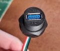
Here's the thing. I've been using this adapter for all of my circuits using a standard USBA to USBA cable without a problem until now:

WhatsApp Image 2023-07-19 at 12.56.22.jpg
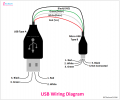
It seems that the adapter in particular that I'm using has the D+ and D- lines inverted. But I've checked the standard colors used in USB wires, and the convention seems to be that the D+ wire is white, whilst the D- wire is green. +5V is always red, and ground is black, btw:

main-qimg-53149f102d782b432052b909dac9ef14-lq.jpg


But after googling a little further, I found some other images showing said colors inverted:

USB Wiring Diagram.png


Anyway, it has always been my understanding that USB communications makes use of a differential signal that travels through the D+ and D- wires. And I thought that since said signal is differential, then the cable's polarities shouldn't matter ... I guess I was wrong.

My thanks to everyone that participated in this thread and helped me solve this nuisance.
 

nsaspook

Joined Aug 27, 2009
13,635
Found the culprit...

The first thing I did was go, again, through each and every single pin connection, as suggested. And I found, again, nothing wrong with the way I did things.

Then, as per Spook's suggestion, I studied the breakout module's schematic and found one inconsistency, which is the use of a 0.47 µF bypass capacitor at the VUSB pin. My circuit lacked said capacitor. But the thing is that ALL of my other circuits lacked said capacitor too and I never had a problem. But I installed said capacitor (and plan on always including it from now on) and still the damn thing didn't work.

So, out of a hunch and a little desperation, I decided to swap the D+ and D- wires to see what happened ... and Lo and behold! ... my computer immediately recognized the device and installed it as a new serial port, as it should have done from the beginning.

Here's the thing. I've been using this adapter for all of my circuits using a standard USBA to USBA cable without a problem until now:

It seems that the adapter in particular that I'm using has the D+ and D- lines inverted. But I've checked the standard colors used in USB wires, and the convention seems to be that the D+ wire is white, whilst the D- wire is green. +5V is always red, and ground is black, btw:


But after googling a little further, I found some other images showing said colors inverted:


Anyway, it has always been my understanding that USB communications makes use of a differential signal that travels through the D+ and D- wires. And I thought that since said signal is differential, then the cable's polarities shouldn't matter ... I guess I was wrong.

My thanks to everyone that participated in this thread and helped me solve this nuisance.
My pal Murphy's law bites again.
 

geekoftheweek

Joined Oct 6, 2013
1,268
Anyway, it has always been my understanding that USB communications makes use of a differential signal that travels through the D+ and D- wires. And I thought that since said signal is differential, then the cable's polarities shouldn't matter ... I guess I was wrong.
When you first plug in your device it will either pull D+ or D- high to designate the connection speed and to let the host know there is a new connection. Having the lines switched will cause a speed mismatch from the beginning.

Edit...
In all the USB cord I cut to connect to the various PICs I've played with with USB built in it's always been green for D+ and white for D-.
 

Thread Starter

cmartinez

Joined Jan 17, 2007
8,304
When you first plug in your device it will either pull D+ or D- high to designate the connection speed and to let the host know there is a new connection. Having the lines switched will cause a speed mismatch from the beginning.

Edit...
In all the USB cord I cut to connect to the various PICs I've played with with USB built in it's always been green for D+ and white for D-.
That explains a lot, Geek ... many thanks for your help.
 
Thread starter Similar threads Forum Replies Date
C Microcontrollers 1
cmartinez General Electronics Chat 12
Top