Manual UP/DOWN counter help

Thread Starter

Aras

Joined Dec 7, 2014
10
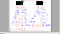
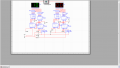
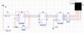
Hey guys, i need some help. Im trying to create manual UP/DOWN counter using 74ls48(or 47 ir only for simulation in multisim) BCD to seven segment decoder, 74ls192 counter. I want when im pressing for example S1 switch this system would count up and by toggling S2 switch to count down. I have done the count up mechanism, but i dont know how to set all things up to count down. Im really newbie in this, and any of your help would help me a lot :)
In the scheme i attached im using 74ls90 decade counter to stop when counter get up to 9 and resets it.
P.S. sorry for my bad english and esthetic of scheme.
 

Attachments

Retiredguy

Joined Feb 24, 2007
28
Aras,
First of all, from what I understand from your post you wish to do, you do not need the 74LS90 at all in your circuit. The 192 will count up and down using the "UP DOWN" inputs of the chip. Tie your switches to those inputs and if you want to count up use the switch tied to the "UP" input and vice versa. And if you want it to only count to 9, you can set up some logic on the outputs to reset or CLR the chip.
 

cmartinez

Joined Jan 17, 2007
8,299
I have done the count up mechanism, but i dont know how to set all things up to count down..
I suggest you download Digital Works and simulate what you want to do, I even think there's an up-down counter circuit already included in the examples. This software helped me a lot in the past to learn basic digital electronics, before getting into MCUs.
 

Thread Starter

Aras

Joined Dec 7, 2014
10
I suggest you download Digital Works and simulate what you want to do, I even think there's an up-down counter circuit already included in the examples. This software helped me a lot in the past to learn basic digital electronics, before getting into MCUs.
I will try this, thank you for advise :)
 

Thread Starter

Aras

Joined Dec 7, 2014
10
I have creater manual UP/DOWN counter, one of them shows 1, other 9, 2 and 8, 4 and 6. And so on. I cant figure out, how to make that one of 7 segment indicator would show me 10 and other 0. "Tower" of AND elements is for indicator to show 1, when other side of indicator shows 0.
Im attaching picture of sheme.
 

Attachments

ScottWang

Joined Aug 23, 2012
7,417
You have two basic errors, the one is that you left the input floating, the second is that you don't have a key debounce.

Google : ttl key debounce
 

cmartinez

Joined Jan 17, 2007
8,299
Thank you for your comments, ill take a look at what you have said :)
Although Scott's comment is perfectly true, I don't think that's where the issue lies, since I doubt that your software analyzes those conditions in detail. I haven't examined your circuit in detail (I use Digital Works) but I'm sure it has to do with the way you connected the overflow/carry signals cascading the counters. Can you post a list of what happens vs what's supposed to happen every time you presse the push buttons?
 

djsfantasi

Joined Apr 11, 2010
9,188
Another error…

It looks like you have the output of the AND gate on the left, tied directly to Ground!

Never connect the output of a gate to either Vcc or Gnd

UPDATE: In your latest schematic, I don't see this problem. I was referring to your first post.
 

cmartinez

Joined Jan 17, 2007
8,299
Ok... there seems to be a number of issues with your circuit.
Let's start with basic chip definitions:
  • 7432N: Or gate
  • 74LS192: BCD up-down counter
  • 74LS48: 7 segment decoder
  • 74LS06: Not gate
  • I am assuming that parts U23 and U24 are 2-digit 7 segment LED displays
Let's begin with this tip: first, erase everything you have on the left, and keep only the side of the circuit leading up to U23. Now, if U3 is a 2-digit 7 segment display, and you need to count from 0 to 99, then you need two 74LS192 chips, and not just one, since each 74LS192 can only count from 0 to 9 before overflowing. The first step is to get rid of the network with all those Or gates and its ending Not gate , and place another 74LS192 connected to the previous 74LS192 in such way that one up-count or down-count will take place if the latter overflows or underflows. Got it?
 

Thread Starter

Aras

Joined Dec 7, 2014
10
Ok... there seems to be a number of issues with your circuit.
Let's start with basic chip definitions:
  • 7432N: Or gate
  • 74LS192: BCD up-down counter
  • 74LS48: 7 segment decoder
  • 74LS06: Not gate
  • I am assuming that parts U23 and U24 are 2-digit 7 segment LED displays
Let's begin with this tip: first, erase everything you have on the left, and keep only the side of the circuit leading up to U23. Now, if U3 is a 2-digit 7 segment display, and you need to count from 0 to 99, then you need two 74LS192 chips, and not just one, since each 74LS192 can only count from 0 to 9 before overflowing. The first step is to get rid of the network with all those Or gates and its ending Not gate , and place another 74LS192 connected to the previous 74LS192 in such way that one up-count or down-count will take place if the latter overflows or underflows. Got it?
Thank you, and one more question. How can i set "Green" 7 segment indicator to show 10(Just like in picture) at the beggining of simulation. I have done the shifting(i dont know how u say, Transfers from younger to an older column. Younger - 9 next 0 and older gets 1)
 

Attachments

cmartinez

Joined Jan 17, 2007
8,299
Thank you, and one more question. How can i set "Green" 7 segment indicator to show 10(Just like in picture) at the beggining of simulation. I have done the shifting(i dont know how u say, Transfers from younger to an older column. Younger - 9 next 0 and older gets 1)
Digit on the right would be the Least Significant Digit (or LSD) and the one on the left would be the Most Significant Digit (MSD)
There are two ways of pre-setting your counter so that it would start at 10:
  • The hard way: design a startup circuit that would feed the MSD counter a 1 at its pre-set inuputs... which I think would be too complicated for what you want to accomplish
  • The easy way: add a button that will pulse the MSD counter independently of the LSD one, so that when you start your simulation you can manually set MSD to 1. You will have to run this button through an 0r gate in which its other input would be the LSD counter's overflow signal, and the output of this or gate would go into the up-count input of the MSD counter.
 

Thread Starter

Aras

Joined Dec 7, 2014
10
Digit on the right would be the Least Significant Digit (or LSD) and the one on the left would be the Most Significant Digit (MSD)
There are two ways of pre-setting your counter so that it would start at 10:
  • The hard way: design a startup circuit that would feed the MSD counter a 1 at its pre-set inuputs... which I think would be too complicated for what you want to accomplish
  • The easy way: add a button that will pulse the MSD counter independently of the LSD one, so that when you start your simulation you can manually set MSD to 1. You will have to run this button through an 0r gate in which its other input would be the LSD counter's overflow signal, and the output of this or gate would go into the up-count input of the MSD counter.
I figured this out, and it was quite simple, i kinda even laugh from it. U5 counter Output CO contact connected with U2 counter Up and A inputs. BO Output connected with Down Input. And B, C, D inputs to ground.
And about range of number avalible. I want to make, that minimum number would be 00 and maximum 10. How can i prevent LSD from counting to 11?
Would be great if you just could tell me how can i search this in google. "Counter number ranges"?
 

cmartinez

Joined Jan 17, 2007
8,299
I figured this out, and it was quite simple
Excelent... what you just did is called cascading the counters. And I'm glad you've got some initiative and are willing to look this up on your own... As to preventing counting beyond 10, here's an idea:
The 74LS192 has 4 outputs (Q0 to Q3) representing the binary form of the actual counted number, So for the number 1, the outputs would be Q0=1, Q1=0, Q2=0, Q3=0, What I would do, is connect the Q0 output of the MSD counter to one input of an XOR gate, and the other input of the XOR gate to the pushbutton. And finally, I'd connect the output of the XOR gate to the upcount input of your LSD counter... If you follow this logic, with the correct set of gates you'd be able to preset any number limit that you wanted.
 

Thread Starter

Aras

Joined Dec 7, 2014
10
Excelent... what you just did is called cascading the counters. And I'm glad you've got some initiative and are willing to look this up on your own... As to preventing counting beyond 10, here's an idea:
The 74LS192 has 4 outputs (Q0 to Q3) representing the binary form of the actual counted number, So for the number 1, the outputs would be Q0=1, Q1=0, Q2=0, Q3=0, What I would do, is connect the Q0 output of the MSD counter to one input of an XOR gate, and the other input of the XOR gate to the pushbutton. And finally, I'd connect the output of the XOR gate to the upcount input of your LSD counter... If you follow this logic, with the correct set of gates you'd be able to preset any number limit that you wanted.
Thank you, its working.. Kind of... The signal of counter is too long comparing with push button.. When push button comes back to its original possition in this case open, signal of counter is still active and XOR creates double signal.. Instead of 9 (when counting down from 10) im getting 8.
 
Top