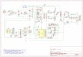
Thanks for the files. I will check the schematic against my power supply and change component references/values where needed. I would love to be able to run a simulation but then i need to find spice info on the transformers (doubtful).
My goal is to add constant current mode without having to modify the power supply itself. No fancy stuff with a microcontroller, pure analog using a ACS712 hall-effect current sensor and analog conditioning to set the output voltage. And a second option, disable the output when a chosen current is exceeded - reset with a pushbutton (as in my very old power supply).
I know these power supplies are also available with a variable current limiting option. We can even modify the ones without by adding/changing a few components at the TL494 but, as i mentioned, i don't want to modify the power supply.
Such a circuit (if it works) should be usable with other (non digitally controlled) power supplies.
There is one error in you Kicad schematic: The wire going down from T2-6 shouldn't connect to the cathode of D5.
Starting from your schematic, i created the schematic of my power supply (Kicad file attached).
There are a few differences:
Power mosfet gate circuit
auxiliary power GND wiring (DK912)

 Facebook
 Google
 GitHub
 Linkedin