Low voltage AC to DC

Thread Starter

davidw

Joined Jan 12, 2009
20
Good afternoon,

I am hoping someone can help with this simple project.

I want to interface my thermostat to a computer to monitor my heating usage. My thermostat has two pins that would be used: Pin (1) Ground and Pin (2) Heating On.

When the heat is on, Pin (2) is +24V AC. When the heat is off the pin is 0V.

The Microcontroller I am using (HC11) recognizes only 0 or 5VDC. How can I convert the 24VAC signal to a clean 0 or 5VDC signal for the microcontroller? I have a separate 5VDC source

My thoughts:
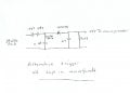
Option 1) Use some kind of relay. Attach the 24VAC and Ground pins to the coil and switch using the 5VDC supply I have. Do they even make relays like this?
Option 2) Use a diode bridge to convert the voltage to DC then a voltage regulator to reduce it to 5VDC.

Any other options? What is the smartest and simplest approach for this? Thank you in advance for your help!
David
 

bertus

Joined Apr 5, 2008
22,278
Hello,

When you want to play it safe, you take the 24 Volt AC, put it in a rectifier bridge, stabelize it with a capcitor.
Take this voltage to drive a led inside a optocoupler (you will need a resistor to limit the current through the led), the ouput of the optocoupler is most times a transistor.
Put the emiitor of the transistor to the ground connection of your microcontroller.
Connect a resistor of 2k2 to collector (this is your output), the other side of the resistor goes to 5 Volt of your microcontroller powersupply.

Now the heating and microcontroller are electricaly seperated.

Greetings,
Bertus
 

Thread Starter

davidw

Joined Jan 12, 2009
20
Thanks for the response Bertus. Which pin would I use to determine if the heating system is on? Specifically, which pin will go +5VDC when the heating is on and 0V when heating is off?

Thanks!
David
 

Thread Starter

davidw

Joined Jan 12, 2009
20
Thanks for the drawing Bertus. I am going to look into those components and make sure I understand that.

studiot - the 24VAC is from the thermostat. It runs on that voltage.

David
 

Thread Starter

davidw

Joined Jan 12, 2009
20
Hi Bertus. I understand your drawing and your solution is simple and elegant. I found the following parts on digikey.com and wanted to confirm with you that these are what you had in mind. You should be able to click on the Digi-Key part number and it will take you to the website.

Description
Man. Part Number
Digi-Key part number
Quantity
Optocoupler
4N35M
4N35MFS-ND
1
Diode bridge
DB101-BP
DB101-BPMS-ND
1
100 uF capacitor
ECA-1JM101
P5193-ND
1
1k5 resistor
RSF100JB-1K0
1.0KW-1-ND
1
2k resistor
RSF100JB-2K0
2.0KW-1-ND
1


Thanks again!!
David
 

studiot

Joined Nov 9, 2007
4,998
studiot - the 24VAC is from the thermostat. It runs on that voltage.
I realise that.

If it runs on 24volts AC it is already isolated from the mains.

The optoisolator is not strictly needed therefore. Also Bertus has shown you grounding the supply to the microcontroller. If you do this you may loose the isolation as the thermostat supply may well be grounded on one side.

However 24v AC = 68 volts peak to peak. A 63 volts capacitor will not be adequate in Bertus circuit.
 

studiot

Joined Nov 9, 2007
4,998
Ideally your input to the bridge from the 24v AC should be capacitively coupled, through say a 100microfarad, 100v capacitor. Then you can replace the optoislator with a simple transistor or a logic gate, schmidt connected. You don't actually need a bridge rectifier a single rectifier or transistor will do, you have plenty of headroom available.
 

studiot

Joined Nov 9, 2007
4,998
Further, in Bertus circuit the capacitor forms a peak detector (sample and hold) which you need to supply signal for heating on.

However the capacitor has no discharge path once the thermostat turns off, so your turn off times will be incorrect.
 

Thread Starter

davidw

Joined Jan 12, 2009
20
Hi studiot,

Interesting you mention that because I do want to record the times the thermostat turns on/off. Would you mind drawing a quick diagram of the circuit your proposed? I am having a hard time visualizing it.

Thanks,
David
 

Thread Starter

davidw

Joined Jan 12, 2009
20
I don't really have much of anything on hand. Just some misc resistors. Assume I have to buy everything so the fewer number of parts the better! Thanks,
David
 

Thread Starter

davidw

Joined Jan 12, 2009
20
Using Bertus's circuit, how long would it take for the "output to microcontroller" go to 0V when the 24VAC goes to 0V (because of the capacitor)?

David
 

bertus

Joined Apr 5, 2008
22,278
Hello,

There will be a little delay. I think it will be about 5 - 10 cycles of the AC.
At 50 Hz 50 - 100 mSec, at 60 Hz 42 - 84 mSec.
The down will be around , 0.75 sec (5 x τ)

Greetings,
Bertus
 

Thread Starter

davidw

Joined Jan 12, 2009
20
Bertus - my system does not need to be that percise on time measurement, so that will be fine! Can you please review the list of part numbers to confirm they will perform as you described in your circuit diagram?

Thanks,
David
 

bertus

Joined Apr 5, 2008
22,278
Hello,

I see in your list that there is a 1.0K resistor, this should be 1.5K.
( it will work with 1.0K but the led will draw more current, i do not know the limit of the 24 volts of the heating system).
I see you have chosen a 50 Volt diode bridge, better use a 200 Volt type at the same price, this can also handle spikes as they occur.

Greetings,
Bertus
 

Thread Starter

davidw

Joined Jan 12, 2009
20
Thanks Bertus. I updated my parts list. Thanks so much for your help! I will post here again if I have any issues building the circuit.

David
 

studiot

Joined Nov 9, 2007
4,998
The following passive network should give you a +5 volt signal whenever there is 24v ac at the input.

I have split the input capacitor into two series ones so that if one fails short circuit you still have protection.

All capacitors are non polarised types, an advantage.

If you require a -5 volts signal, invert the diode.

Slight trimming of the input divider may be necessary.
 

Attachments

bertus

Joined Apr 5, 2008
22,278
Hello Studiot,

Is there a 3M3 resistor at the output ? (it is drawn like a coil).
The time constant (without the input resistance of the microcontroller) is 3 Sec.
The total decay time will be 5 X 3 Sec = 15 Sec.

Greetings,
Bertus
 
Top